

Table of Content
- Introduction
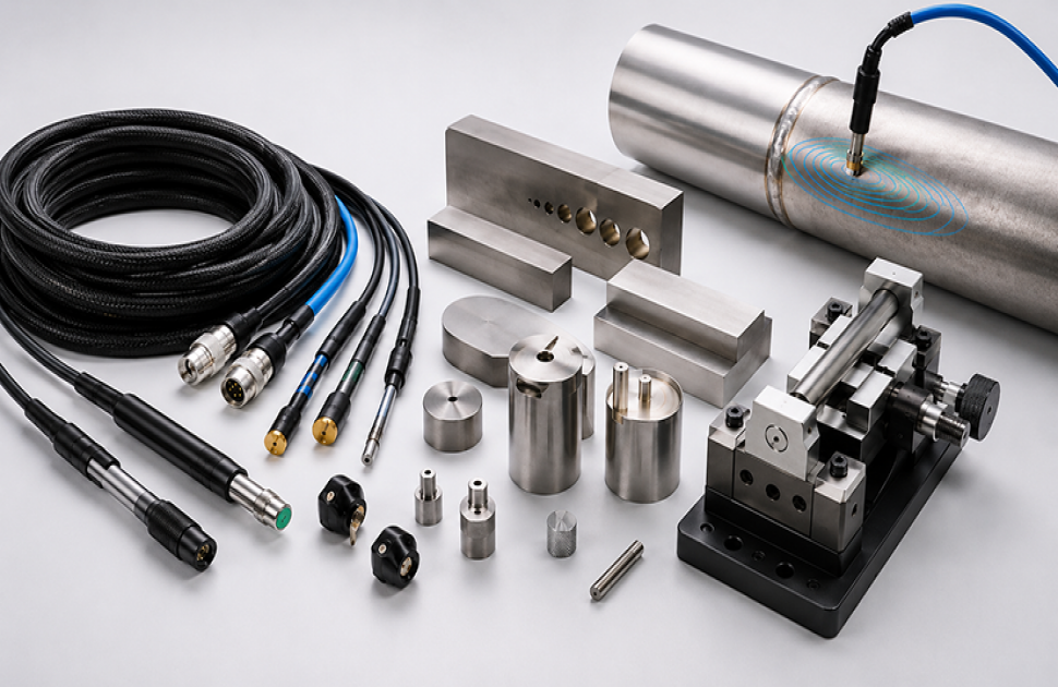
- What Counts as an Eddy Current Testing Accessory?
- Four Levels of Accessory Compatibility
- Probe Cables & Connectors
- Reference and Calibration Standards
- Probe Holders, Guides and Fixtures
- Scanners, Encoders and Tube-Inspection Accessories
- Consumables, Data-Storage and Field-Support Items
- Matching Accessories to Your Procedure
- Building a Complete Eddy Current Inspection Kit
- Where to Source Eddy Current Accessories
- Conclusion
- FAQ
Introduction
Eddy current testing accessories — probe cables, reference standards, calibration blocks, fixtures, scanners and encoders — decide whether a technically sound eddy current inspection produces defensible results. The instrument and probe do not alone determine the validity of an inspection. The supporting infrastructure around them carries the signal, controls the conditions under which it is generated, and supplies the reference against which it is judged.
A damaged cable introduces noise. An inappropriate reference standard produces incorrect calibration values. Inconsistent probe positioning destroys repeatability. In each of these cases the accessory, not the instrument, is the source of the failure — and the problem may go undetected until an audit or a missed indication reveals it.
This guide covers the selection, verification and upkeep of the accessories that surround the instrument and probe: cables and connectors, calibration blocks and reference standards, fixtures and scanning equipment, and the field-support items that keep an inspection running.
This guide covers the accessories side of eddy current testing, for the full picture of how ECT works from probe design to signal interpretation, see our complete explainer.
→ Read: Eddy Current Testing Explained
What Counts as an Eddy Current Testing Accessory?
For the purposes of this guide, the instrument and probe are treated as the core of the inspection system. Accessories are the components used alongside the instrument and probe to set up, calibrate, position, operate and document an inspection.
This includes:
- Probe cables and connectors
- Reference standards and calibration blocks
- Probe holders, guides and fixtures
- Scanners, encoders and tube-inspection accessories
- Protective sleeves, caps and other consumables
- Data-storage and field-support items
The eddy current field is induced and detected only by the probe coil or coils — reflection and array probes use separate drive and sense windings. Accessories affect signal quality, calibration validity and repeatability because they either carry that signal, control the conditions under which it is generated, or supply the reference against which it is evaluated.
Four Levels of Accessory Compatibility
Before any accessory is bought, borrowed or substituted, it has to clear four separate compatibility checks. Most substitution errors happen because only the first one is tested.
Level | Question to answer | Fails when |
|---|---|---|
Mechanical | Does it physically fit? | Wrong connector type, probe will not seat, fixture does not match the geometry |
Electrical | Does the system respond the same way? | Impedance mismatch, inadequate shielding, changed cable length |
Metallurgical | Does the reference represent the part? | Conductivity or permeability mismatch between block and component |
Procedural | Does the approved procedure permit it? | No certification, no traceability, item not specified in the procedure |
An accessory can satisfy the mechanical requirement and still fail the other three. A connector that mates correctly proves only that it fits. The sections below work through each accessory group against these four levels.
Probe Cables & Connectors
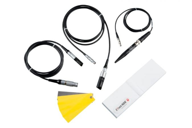
The eddy current probe cable is one of the most overlooked items in an inspection setup. It carries the drive and return signals between instrument and probe, and it can degrade the measurement in four ways: unsuitable construction, excessive length, inadequate shielding, or physical damage.
Cable Length & Signal Performance
Cable length changes the electrical characteristics of the system. Added length increases the distributed capacitance and inductance of the probe circuit. This additional reactance shifts the tuned response of the probe-cable combination as length rises, which can lower the signal-to-noise ratio, rotate the phase angle and degrade sensitivity. The effect becomes more noticeable at higher operating frequencies and with absolute probes, so cable length must be treated as a calibrated component of the system rather than a convenience option.
Base cable selection on the recommendation of the equipment manufacturer and on the approved inspection procedure.
Impedance Matching and Shielding
The cable must suit both the probe and the instrument. If the impedance characteristics are not appropriate, the system response changes and the calibration may no longer represent the actual inspection configuration.
Shielding matters just as much. Eddy current testing detects very slight variations in coil impedance — that is, in the resistive and inductive components of the probe circuit impedance. These variations are often very small relative to the total circuit impedance, so external electromagnetic interference from motors, welding sets, VFDs and radio transmitters can easily register as noise. Properly grounded and shielded cable assemblies reduce this pickup and hold a steady noise floor throughout the examination.
Connectors and Mating
Connectors must be the correct type for the instrument and probe, and must seat securely for the duration of the inspection. Damaged pins, loose connections, contamination and repeated improper mating all cause intermittent contact.
Protect connectors from mechanical stress. Pulling a cable by its connector rather than by the cable body loads the pin contacts and solder joints, and will eventually weaken the connection.
Flax Life and Common Damage Modes
Cables deteriorate over time through repeated bending, twisting, crushing, abrasion and over-pulling. Pay particular attention to the areas near connectors, where repeated flexing concentrates.
Common indications of a cable problem are:
- Signal drift
- Intermittent signal response
- Elevated noise floor
- Unstable calibration
- Unexpected amplitude changes
- Signal loss when the cable is moved
Changing the probe cable alters the electrical connection and can alter the system response, so re-calibrate the inspection system after any cable change.
Reference and Calibration Standards
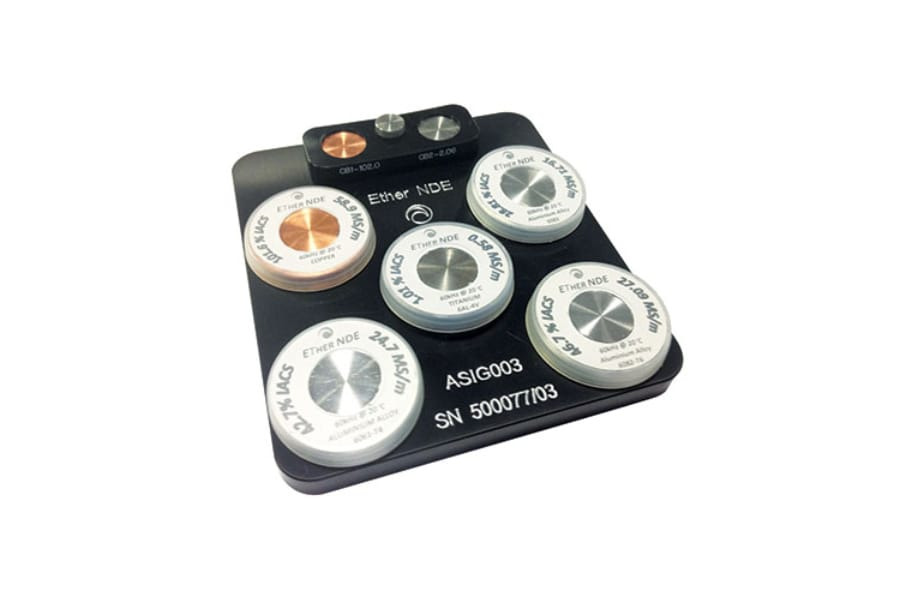
An eddy current reference standard is a physical artifact with known and controlled features, such as material properties, geometry, and artificial discontinuities of set size and placement. It establishes or confirms the response of the inspection system before, during and after examination, providing a known characteristic or property against which the instrument and probe are compared.
Reference standards vary according to the application.
Common types include:
- Tube reference standards containing machined artificial discontinuities along the tube length
- Drilled-hole calibration blocks
- Conductivity standards
- Coating-thickness shims
- Artificial discontinuity standards
- Material-specific reference specimens
An eddy current calibration block should represent the characteristics of the part being inspected and carry the features specified in the inspection procedure or the applicable inspection standard. See our guide to eddy current calibration for the calibration sequence itself.
Conductivity Matching and Material Matching
Material selection determines whether the calibration is valid. Electrical conductivity, magnetic permeability and geometry govern the eddy current response. A reference block made from material markedly different from the test component will not represent what happens in the field, which is why material and conductivity matching is essential.
Because the calibration then represents the reference block rather than the component, the indications may be invalid even when the instrument is fully calibrated and the readings are stable and reproducible. A mismatched standard yields results that look defendable but are not — repeatability and accuracy are not the same thing.
Standards and Conformance
Specify the dimensions, artificial discontinuities and tolerances of a reference standard in accordance with the applicable specification or inspection procedure. Do not select a block simply because it is available on the market.
Where the controlling procedure or code invokes a specification, conformance is required, not optional — and the scope of the document you cite matters:
- ASME BPVC Section V, Article 8 covers eddy current examination of tubular products. Cite it for tube work, not as a blanket reference for all eddy current inspection.
- ASME BPVC Section V, Article 26 contains the adopted eddy current standards (the SE-series documents) that apply more broadly, including surface, weld and bolt-hole applications.
- ASTM E543 sets requirements for agencies performing non-destructive examinations.
- The ISO 15548 series covers the characteristics and verification of eddy current equipment — instruments (Part 1), probes (Part 2) and systems (Part 3).
The reference standard must satisfy the discontinuity dimensions, tolerances, material and certification requirements of whichever specification the procedure refers to. A "similar" or "equivalent" standard cannot be used unless the relevant quality system has explicitly assessed and approved it. See the applicable guide to eddy current testing standards for fuller coverage.
Traceability and Certification
Certify reference standards appropriately and document traceability where required. Documentation can establish:
- Material identification
- Relevant physical properties
- Artificial defect characteristics
- Manufacturing or inspection information
- The status of the calibration or verification
- Traceability to recognized standards
During audits, quality reviews and regulatory evaluations, this documentation defends the inspection outcome.
Storage and Handling
Safeguard reference standards against corrosion, damage, contamination and unauthorized alteration. Artificial defects must not be damaged or altered — even minor changes to a machined defect affect the calibration response.
Keep standards in appropriate protective boxes or storage locations and check them at intervals set by the applicable quality system.
Which ASME, ASTM or ISO specification actually governs your reference standard? See our breakdown of which eddy current testing standard applies to your application.
→ Read: Eddy Current Testing Standards: Which One Applies to You
Probe Holders, Guides and Fixtures
One of the key goals of an eddy current inspection is to reproduce the inspection conditions every time. Fixtures control probe position, movement and lift-off.
In freehand scanning, slight variations in operator angle or hand pressure directly cause signal fluctuation. A probe holder or guide maintains far more consistent probe orientation and lift-off. Holders earn their place on long scans where operator fatigue becomes an issue, on repetitive geometry, and wherever the procedure imposes strict lift-off limits.
Fixtures reduce operator-dependent variation. They support consistent:
- Probe orientation
- Scan speed
- Probe position
- Lift-off
- Scan path
Controlling these variables improves repeatability between successive scans and between different operators.
Scanners, Encoders and Tube-Inspection Accessories
Scanners
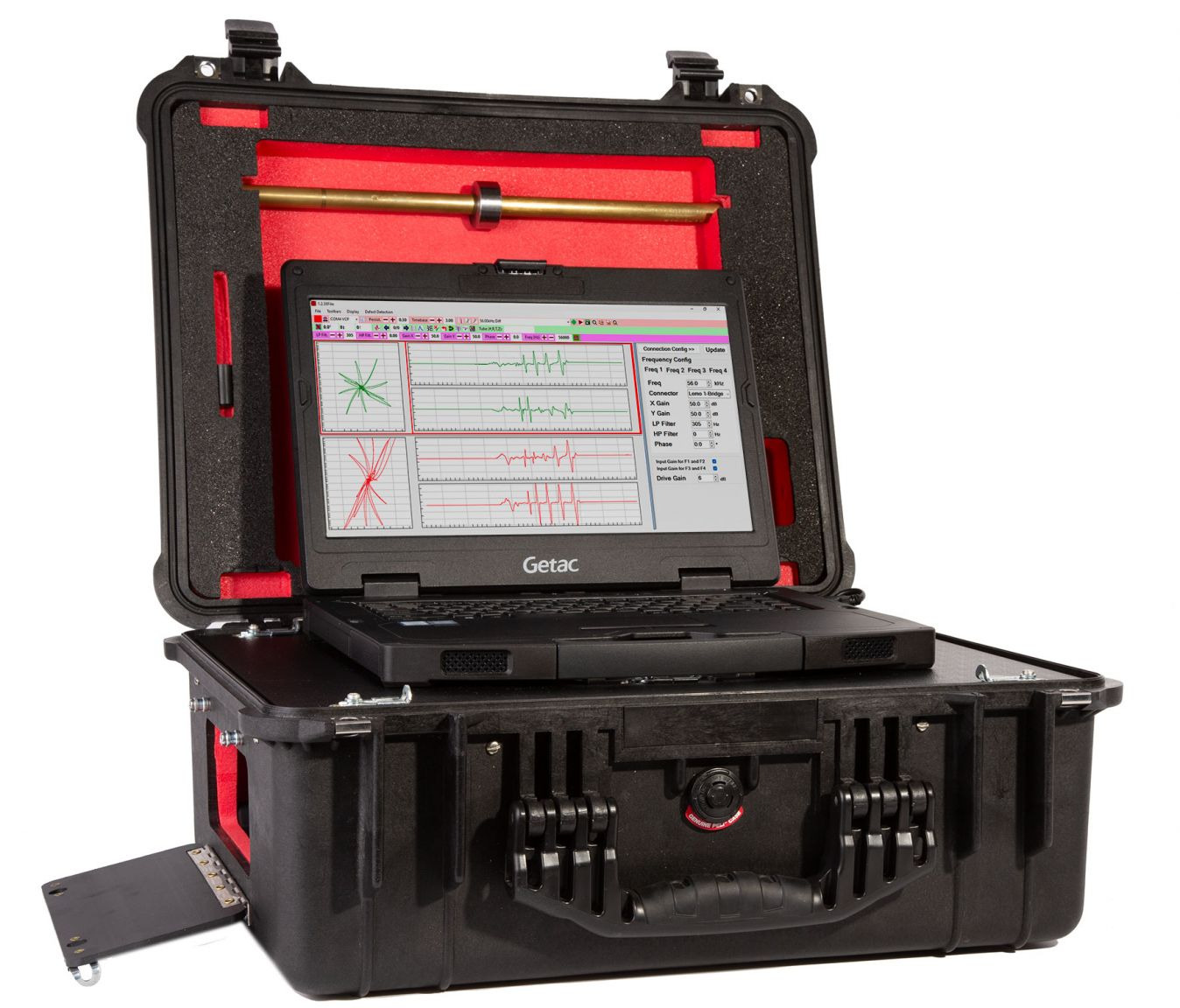
A scanner moves the probe in a controlled manner. Scanners may be manually driven, motorized, or integrated into a fully automated inspection system.
Rotating scanners typically handle cylindrical parts, and purpose-built scanning fixtures can be made for welds, bolt holes, surfaces and other shapes.
Positional Data and Encoders
An encoder adds positional information to the inspection record. Amplitude and phase remain the two key metrics used to assess an indication; the encoder adds a third dimension — position — that ties each indication to a physical location on the component rather than to a moment in time on the scan.
This supports:
- Mapping indications
- Generating inspection reports
- Re-inspection
- Analyzing outcomes over time
- Identifying defects for follow-up examination
Together, a scanner and encoder deliver controlled probe movement and location-specific inspection data. Encoders also serve manual encoded scanning, where the operator moves the probe by hand while position is still recorded — enabling C-scan imaging and dependable re-inspection without full automation.
Tube-Inspection Accessories
Tube inspection has its own accessory set, built around getting the probe down the tube in a controlled, repeatable way:
- Tube pushers and pull-through systems, manual or motorized
- Centering devices and guide tubes that hold the probe on the tube axis
- Flexible shafts and drive units for rotating-probe techniques
- Encoded pushers, where the procedure requires a positional record
- Tube-sheet mapping accessories for locating each tube in the bundle
These items rarely sit in the signal path, but they govern probe centring, pull speed and position — all of which affect the consistency of the data.
Consumables, Data-Storage and Field-Support Items
A complete inspection kit also includes the supporting supplies that make fieldwork feasible. Most of these — cases, cable reels, storage media — sit outside the signal path entirely. Two exceptions deserve attention. Protective sleeves and wear caps sit between the coil and the test surface, so they change lift-off and must be fitted during calibration if they are to be used during inspection. Power supply matters too: on some instruments, a low battery can affect drive stability.
Common field-support items are:
- Protective sleeves and caps
- Power accessories and spare batteries
- Protective equipment cases
- Cable reels and cable-management accessories
- Cleaning and maintenance items
- Data-storage devices
- Laptop or tablet accessories
- Software and reporting tools
Cases prevent mechanical damage in transit, and wear caps and sleeves protect probes through repeated inspections. Spare batteries and power accessories avoid unnecessary interruptions in the field.
Adequate data-storage capacity matters wherever inspections produce large encoded data sets, images or inspection reports. Account for these supporting accessories when specifying the full inspection kit, rather than adding them after the equipment has been bought.
Matching Accessories to Your Procedure
Do not choose accessories without considering how they will be used in the inspection.
An approved written procedure may specify the probe, the operating frequency, the reference standard, the calibration method and the calibration interval. Once established, these requirements limit which accessories can be substituted.
A given reference standard may be unusable if its material, artificial discontinuities or certification do not comply with the procedure. Likewise, changing the probe cable or the scanning arrangement means the system must be recalibrated or verified.
Check the governing requirements before buying or replacing any accessory.
Building a Complete Eddy Current Inspection Kit
The right kit depends on the application. A complete kit contains everything needed to connect, calibrate and position the instrument and probe, and to document the inspection.
Accessory | Surface | Tube | Bolt-hole | Weld |
|---|---|---|---|---|
Probe | Surface or pencil probe | Bobbin, array or rotating probe | Bolt-hole probe | Weld probe or array |
Compatible probe cable | Required | Required | Required | Required |
Reference standard | Application-specific surface standard | Tube standard with machined discontinuities | Bolt-hole block with reference notches | Weld-specific standard |
Holder, guide or fixture | Probe holder or guide | Centering devices and guide tubes | Bolt-hole guide fixture | Holder or scanning fixture |
Scanner | Optional | Tube pusher or pull-through system | Rotating scanner, typically required | Weld scanner, where used |
Encoder | Where positional record required | Where positional record required | For depth and position recording | For positional mapping |
Protective sleeves / wear caps | Recommended | — | — | Recommended |
Data storage and reporting | Required | Required | Required | Required |
The final kit always depends on the approved inspection procedure, the component geometry and the governing standard. The goal is not to collect the most accessories, but to assemble a compatible, calibrated and repeatable inspection system.
The right accessory kit depends on which ECT technique you're running — see how conventional, array, pulsed and other variants differ in equipment needs.
→ Read: Types of Eddy Current Testing
Where to Source Eddy Current Accessories
Once the procedure has defined what the kit needs, sourcing becomes a matching exercise against the four compatibility levels above — and the practical questions change:
- Cables and connectors are usually instrument-specific. Confirm the connector type, length and shielding specification against the manufacturer's documentation before ordering, and re-calibrate on receipt.
- Reference standards and calibration blocks are frequently custom-manufactured to the procedure. Ask the supplier for the certification package — material identification, defect dimensions, tolerances and traceability — before purchase, not after delivery.
- Fixtures, scanners and encoders should be specified against the component geometry and the recording requirements of the procedure.
Conclusion
Accessories are not incidental to eddy current testing; they determine whether the inspection succeeds. Probe cables and connectors control the integrity of the electrical signal. Reference standards form the basis of every calibration. Fixtures, scanners and encoders govern probe orientation and deliver reproducible results.
Compatibility remains the deciding factor, and it has to clear all four levels set out earlier — mechanical, electrical, metallurgical and procedural. Passing one proves nothing about the other three.
Treating accessories as part of the inspection system, rather than as optional extras, improves calibration stability, repeatability and traceability — and with them, confidence in the result. Before substituting any cable, standard or fixture, check what the approved procedure actually permits
FAQ
What are the accessories used in eddy current testing?
Eddy current accessories are the supporting parts used alongside the instrument and probe: probe cables and connectors, reference standards and calibration blocks, probe holders and fixtures, scanners and encoders, tube-inspection accessories, and field-support items such as protective caps, data-storage media and transport cases.
Why are eddy current probe cables important?
The probe cable carries the drive and return signals between probe and instrument. Its length, electrical characteristics, shielding quality and physical condition all affect signal stability, noise level and the validity of the calibration
Why does an eddy current system need recalibration after changing a cable?
Because a different cable changes the electrical characteristics of the circuit — chiefly its distributed capacitance and inductance — and therefore the system response. Recalibrate to the applicable procedure after any cable change, including a same-length replacement.
What is an Eddy Current Reference Standard?
A physical artifact with known properties, used to establish or confirm the response of an inspection system. Depending on the application, it may contain artificial discontinuities or exhibit a known material property such as conductivity.
What is an eddy current calibration block?
A reference specimen with known characteristics, used to calibrate or verify an eddy current inspection system. Its material, features and dimensions must comply with the relevant procedure or governing standard.
Why should the reference standard match the test material?
Because conductivity and permeability govern the eddy current response. A mismatched block can produce a calibration that is stable and repeatable, yet inaccurate for the component actually being inspected.
Which ASME standard applies to eddy current reference standards?
It depends on the application. ASME BPVC Section V, Article 8 covers eddy current examination of tubular products; the eddy current standards adopted for broader use sit in Article 26. Always work from the specification invoked by the controlling procedure.
What is the role of eddy current scanner / encoder?
The scanner controls or assists probe movement; the encoder records position. Used together, they improve scan repeatability and tie each indication to a location on the component.
Can any compatible accessory be substituted during an inspection?
Not necessarily. An approved procedure may specify particular probes, cables, reference standards, fixtures or calibration requirements. Evaluate and approve any substitution against the procedure and the quality system before use.

There are no comments yet!