
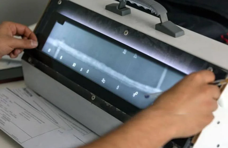
Table of Content
- Introduction
- How radiography works
- Radiation sources
- Detectors: film, CR and DR
- Computed tomography (CT)
- Image quality indicators and image quality
- Exposure and technique
- Interpretation
- Codes and standards
- Radiation safety
- Choosing film, CR, DR or CT
- Conclusion
Introduction
Radiographic testing (RT) remains one of the most reliable methods for inspecting the inside of a weld or casting. It provides you with an image, clearly displays volumetric defects like slag and porosity, and a good radiograph is simple for a second reviewer to verify. What has changed is the detector. Computed radiography (CR), digital radiography (DR), and computed tomography (CT) have joined film, and they all alter how the work is set up, exposed, interpreted, and stored.
This guide is intended for RT technicians and QA managers who approve their findings. Radiation sources, film and digital detectors, image quality indicators (IQIs), exposure technique, interpretation, radiation safety, and the codes that connect it all are all covered. The values below are for orientation and should not be used in place of the code text; always adhere to the code edition and procedure specified in your contract.
How radiography works
The radiation goes through the part and is absorbed depending on the density, atomic number and thickness of the material. Where there is less material, such as a pore or lack of fusion, more radiation passes through, and the detector records a darker area on film or a higher signal on a digital image. Contrast is that difference.
Two additional concepts influence all exposures:
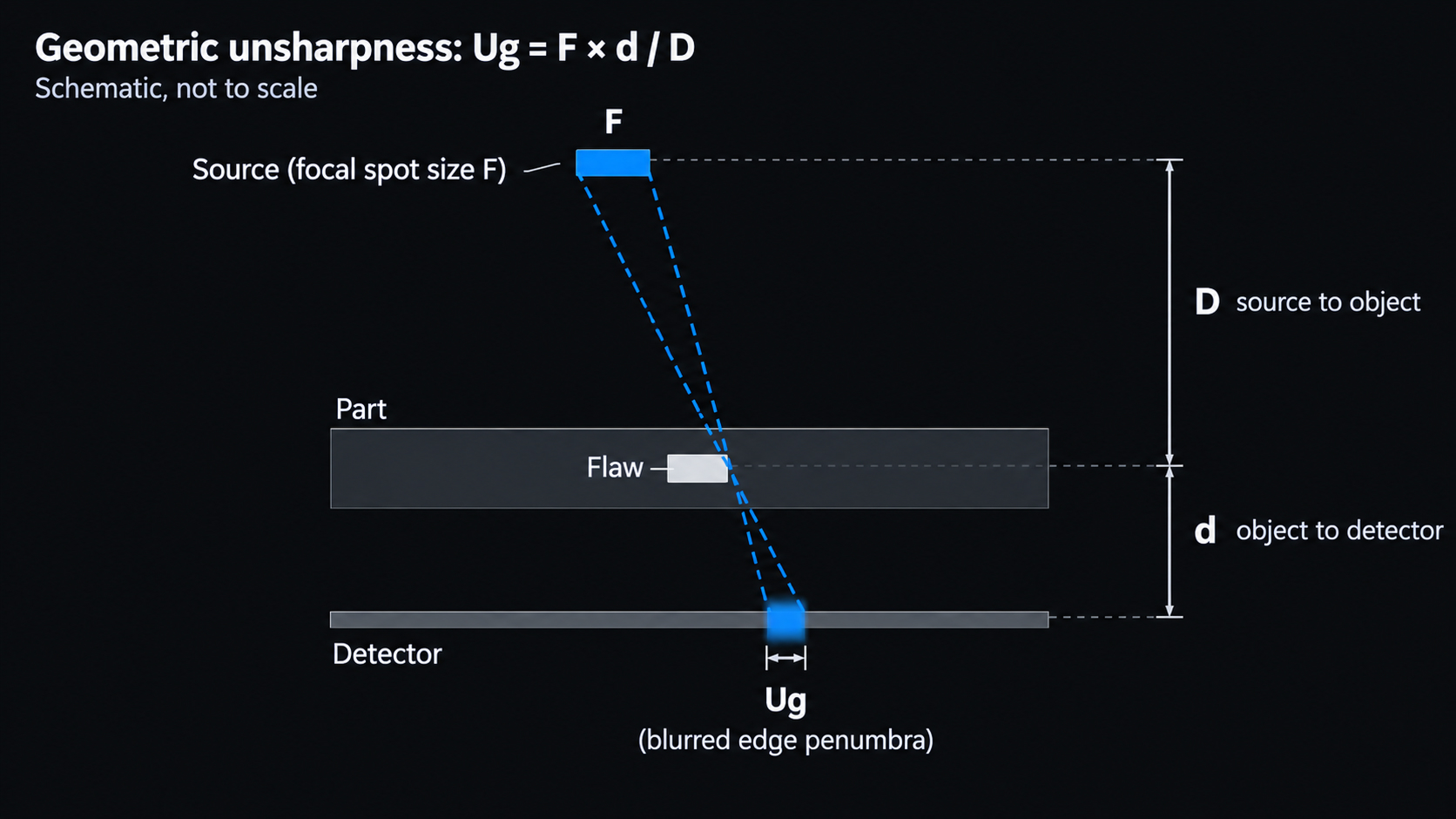
- Unsharpness.The source itself has a physical size which causes edges to become hazy. The formula for geometric unsharpness is Ug = F × d / D where F is the size of the source (focal spot), d is the distance from the object to the detector and D is the distance between the source and the object. It is decreased by a smaller source, a longer source distance and a detector close to the part.
- Inverse square law.The intensity decreases as the distance squared. The intensity is reduced to a quarter and the exposure time becomes four times as great if the distance from the source doubles. The same law applies to radiation safety.
Thickness of materials is usually expressed in terms of half-value layer (HVL): a thickness that reduces the intensity to half. The intensity after n half value layers is (1/2)ⁿ of the original intensity.
Radiation sources
X-ray tubes
A continuous spectrum of energy is produced by X-ray tubes. Penetration is controlled by the tube voltage (kV), while intensity is controlled by the tube current (mA). Higher kV penetrates thicker portions but flattens contrast; lower kV produces greater contrast. While constant-potential units in shielded enclosures handle shop operations, portable directional and panoramic tubes are frequently used in the field. Microfocus tubes are utilized for CT and fine detail because of their very small focal spots. Linear accelerators generate megavolt-range X-rays for extremely thick sections.
X-rays can be switched off, which is a major safety advantage. The trade-offs are size, the need for power and cooling, and difficult access in the field.
Gamma-ray isotopes
Sealed radioactive isotopes stored in shielded exposure devices are known as gamma sources. They are the go-to option for pipeline and field operations because they are small and require no electricity. Exposure times increase as the source ages since they emit radiation continuously and decay over time.
Isotope | Half-life | Gamma energy | Typical steel thickness |
|---|---|---|---|
Selenium-75 | About 120 days | Average about 0.22 MeV | About 3–29 mm (0.1–1.1 in.) |
Iridium-192 | About 74 days | About 0.2–0.6 MeV (average about 0.38 MeV) | About 12–63 mm (0.5–2.5 in.) |
Cobalt-60 | About 5.27 years | 1.17 and 1.33 MeV | About 50–150 mm (2–6 in.) |
The thickness ranges are typical working ranges; the exact limits are set by codes and procedures. The daily workhorse is Iridium-192. Selenium-75 requires less shielding and provides superior contrast on thinner areas. Heavy parts are handled by Cobalt-60 at the expense of significantly heavier shielding and reduced contrast.
Detectors: film, CR and DR
Film
Film is still the reference many codes were written around. Radiation hits the silver halide emulsion, typically in front and behind with lead screens for image enhancement and reduced scatter. The image is permanently read on an illuminator after chemical processing.
Key points:
- Film system class. Film is grouped with its screens and processing in ASTM E1815 or ISO 11699-1. Slower, finer-grained classes produce higher quality images, but require longer exposures.
- Density. The degree of darkness of the film is measured by its optical density. The minimum density is 1.8 for X-ray and 2.0 for gamma for a single-film view and the maximum density is 4.0 according to ASME Section V, Article 2. For composite viewing of multiple films, each film in the set must be at least 1.3. The density, anywhere in the area of interest, should not deviate by more than 15% or +30% from the density through the IQI.
- The step wedge is used to check the accuracy of densitometers.
- Quality and record life is affected by processing and storage. Poor archiving and chemical artifacts are the usual causes of rejected and unreadable films, as is fog.
Computed radiography (CR)
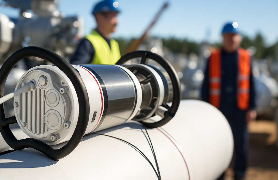
CR replaces film with a reusable **phosphor imaging plate**. Radiation stores a latent image in the plate, a laser scanner reads it out as a digital image, and the plate is erased and reused. CR works with the same kind of exposure setups as film, so it is often the easiest step from film to digital. It needs no darkroom chemicals, can reduce exposure times depending on the image quality class required, and gives a wide dynamic range, so one image can cover a wider range of thicknesses.
CR system performance is classified under ASTM E2446 and ISO 16371-1, and practice is covered by ASTM E2033 and ISO 16371-2. ASME Section V, Article 2 has a mandatory appendix for radiography using phosphor imaging plates. Plates wear and scratch with use, so they need regular inspection and replacement.
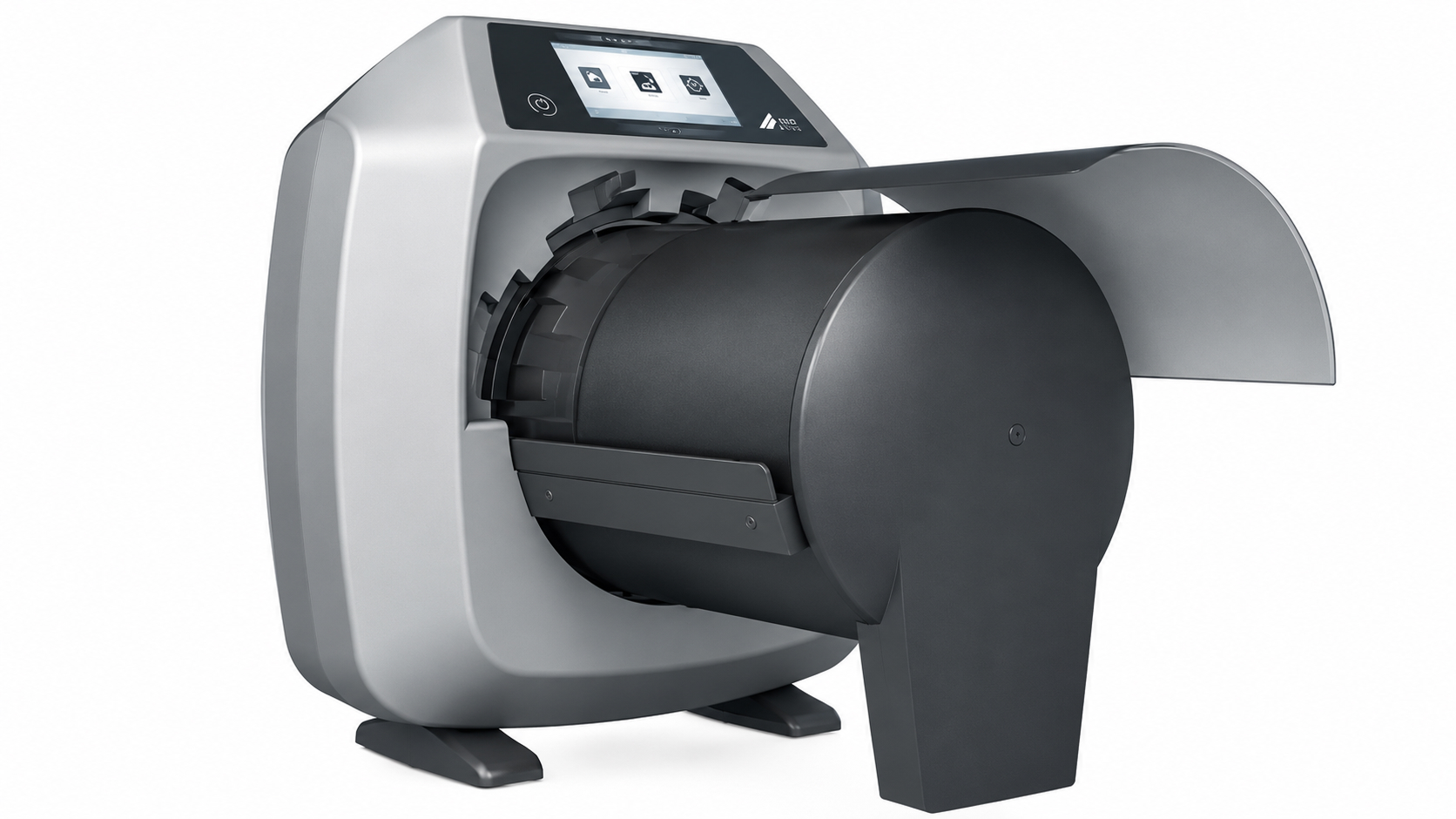
Image source: DÜRR NDT
Digital radiography (DR)
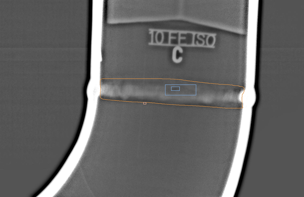
DR uses a **digital detector array (DDA)**, a flat panel that converts radiation into a digital image in seconds. Most panels are indirect: a scintillator converts X-rays to light, which a photodiode array reads. DR gives the fastest workflow, near-real-time images and excellent image quality, but the panels are rigid, expensive and need care in the field. Bad pixels must be mapped and corrected, and panel performance must be checked over time.
DDA characterization and practice are covered by ASTM E2597 and ASTM E2698, with long-term performance monitoring in ASTM E2737. ISO 17636-2 covers digital radiography of welds, and ASME Section V, Article 2 includes a mandatory appendix for digital radiography.
Film, CR and DR compared
Film | CR | DR | |
|---|---|---|---|
Detector | Film with lead screens | Reusable phosphor imaging plate | Flat-panel digital detector array |
Image available | After chemical processing | After laser scanning | Within seconds |
Flexibility | Flexible, cut to size | Flexible plates | Rigid panels |
Dynamic range | Narrow | Wide | Wide |
Consumables | Film and chemicals for every exposure | Plates reused many times | Detector reused |
Image quality measure | Density and IQI | IQI, SNRN and basic spatial resolution | IQI, SNRN and basic spatial resolution |
Records | Physical film archive | Digital files | Digital files |
Switching detectors changes your workflow, cost and image quality. Here's the complete comparison of digital and film radiography and where each one wins.
→ Read: Digital vs Film Radiography: Advantages
Computed tomography (CT)
CT takes hundreds or thousands of radiographic projections as the part rotates (or as the source and detector move around it) and reconstructs them into a three-dimensional volume. Instead of a single shadow image, you get slices through the part in any direction, with flaws located in three dimensions and measurable.
CT is especially useful for castings, additive-manufactured parts, assemblies, composites and dimensional measurement. Its limits are part size, scan time, cost and data volume, and it is mainly a shop or laboratory technique rather than a field one. Practice and image quality are covered by ASTM E1441 (guide) and ASTM E1570 (practice), and by the ISO 15708 series.
Image quality indicators and image quality
An IQI proves that the radiograph is sensitive enough to show the detail the code requires. It doesn't measure flaw size. The main types are:
- Wire IQIs (ASTM E747, ISO 19232-1): a set of wires of increasing diameter. The essential wire must be visible.
- Hole-type (plaque) IQIs (ASTM E1025): a shim with holes of 1T, 2T and 4T diameter, where T is the IQI thickness. In a "2-2T" quality level, the IQI is 2% of the part thickness and the 2T hole must be visible.
- Step-hole IQIs (ISO 19232-2): steps of increasing thickness, each with holes.
- Duplex wire IQIs (ISO 19232-5, ASTM E2002): wire pairs used to measure total image unsharpness and the basic spatial resolution (SRb) of digital images.
Under ASME Section V, Article 2, the IQI is selected from the thickness of the material being radiographed, including allowable weld reinforcement, and is normally placed on the source side. Where that isn't practical, it may be placed on the film side with a lead letter "F" next to it.
Digital images need more than an IQI. ISO 17636-2 also sets minimum values for the **normalized signal-to-noise ratio (SNRN)** and maximum values for basic spatial resolution, depending on the testing class. Contrast-to-noise ratio (CNR) is also used to judge whether a flaw will stand out from the noise. Simply increasing brightness or contrast on screen doesn't improve these values; only a better exposure does.
Exposure and technique
A good exposure starts with the right source and geometry:
1. Choose the energy. Use the lowest kV, or the lowest-energy isotope, that penetrates the section. That gives the best contrast.
2. Set the geometry. Check geometric unsharpness against the code limit. ASME Section V, Article 2 gives maximum values of 0.020 in. (0.51 mm) for material under 2 in. (51 mm) thick, rising to 0.030 in., 0.040 in. and 0.070 in. for thicker sections. Check the edition you work to.
3. Calculate the exposure. Use an exposure chart for the source, detector and material. X-ray exposures are expressed in mA·min, and gamma exposures in Ci·min (or GBq·min), corrected for source decay.
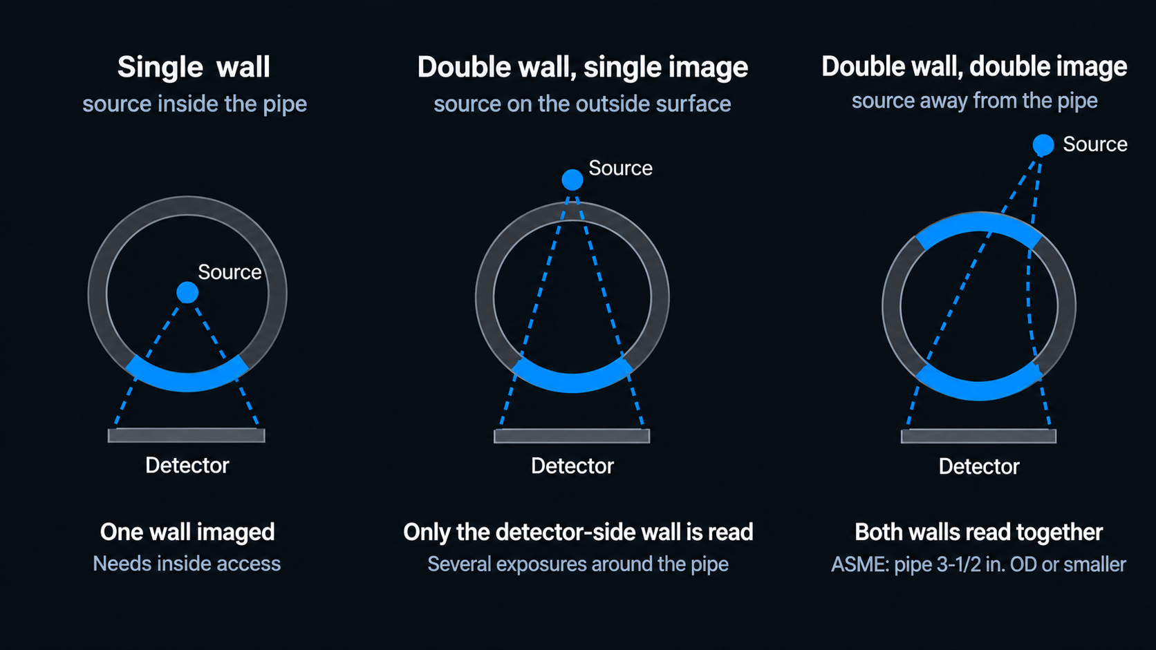
4. Pick the pipe technique. Single-wall exposures give the best image when the inside is accessible. Double-wall, single-image (DWSI) techniques image the wall nearest the detector. Double-wall, double-image (DWDI) techniques image both walls together; ASME Section V limits DWDI to pipe 3-1/2 in. (89 mm) outside diameter or smaller.
A worked example: an Iridium-192 source with a 3 mm focal spot is placed 600 mm from the source side of a 25 mm plate, with the detector directly behind it, so d is 25 mm. Ug = 3 × 25 / 600 = 0.125 mm, or about 0.005 in., well inside the 0.020 in. limit for that thickness.
Interpretation
Interpretation is only as good as the viewing conditions. For film, that means a high-intensity illuminator, masking to cut glare, and subdued background light. For CR and DR, it means a calibrated, high-resolution monitor, a suitable viewing environment and software that records every adjustment made to the image.
Before looking for flaws, confirm that the image is valid: correct identification and location markers, IQI sensitivity met, density or SNRN within limits, and no artifacts in the area of interest. Then look at the weld. Common appearances on a film radiograph are:
Discontinuity | Typical appearance |
|---|---|
Porosity | Dark, round or slightly elongated spots, alone or in clusters |
Slag inclusions | Dark, irregular shapes, often along the fusion line or between passes |
Incomplete penetration | Dark, straight line at the root, usually centered |
Lack of fusion | Dark line, often along the bevel edge; may be faint if not aligned with the beam |
Cracks | Fine, dark, often branching or wavy lines; may be very faint |
Tungsten inclusions | Light (bright) spots, because tungsten is denser than steel |
Burn-through and excess penetration | Dark area at the root (burn-through) or light area (excess penetration) |
Undercut | Dark line along the toe of the weld |
On a digital image, the gray scale may be inverted depending on the software, so check the convention before you read.
Planar flaws such as cracks and lack of fusion are detected best when they lie roughly parallel to the beam. If they are tilted, they can be faint or invisible. That's the main reason radiography is often supplemented by ultrasonic testing on critical welds.
A valid image is only half the job. Here's the complete guide to reading weld radiographs and recognising each discontinuity.
→ Read: Weld Radiograph Interpretation Guide
Codes and standards
Technique standards tell you how to radiograph. Construction codes tell you what to radiograph and what is acceptable.
Purpose | Common references |
|---|---|
Technique | ASME Section V, Article 2; ISO 17636-1 (film) and ISO 17636-2 (digital) for welds; ASTM E94, E1742 and E1032 |
Film classification | ASTM E1815; ISO 11699-1 |
CR | ASTM E2446, E2033 and E2007; ISO 16371-1 and -2 |
DR | ASTM E2597, E2698 and E2737 |
CT | ASTM E1441 and E1570; ISO 15708 series |
IQIs | ASTM E747, E1025 and E2002; ISO 19232 series |
Acceptance | ASME Section VIII Division 1, UW-51 and Appendix 4 (rounded indications); ASME B31.3, Table 341.3.2; AWS D1.1, Clause 8; API 1104; ISO 10675-1 |
Personnel are qualified to ISO 9712 or an employer-based scheme such as ASNT SNT-TC-1A. Radiation safety training and certification are separate requirements, set by the national regulator.
Radiation safety
One of the most risky NDT activities is radiography. All programs are developed around ALARA: As low as reasonably achievable through time, distance and shielding.
- Time : dose is related to the exposure time, so try to minimize exposure time next to the source.
- Distance : the inverse square law is to move away – move away is the best protection.
- Shielding: collimators, lead and concrete reduce dose. Each half-value layer halves it.
Each program should also have:
- Controlled boundaries. The exposure area is cordoned off with survey-fitted barriers, signs and warning lights.
- Monitoring. Each radiographer has a personal dosimeter, and a direct-reading dosimeter and alarming rate meter in the field. A calibrated survey meter is employed to verify boundaries and verify source is completely contained within a shielded container after each exposure.
- Dose limits. ICRP guidelines for occupational exposure: 20 mSv per year averaged over 5 years (maximum 50 mSv per year), and for the public 1 mSv per year. The national limit differs, for example, in the USA, it is 50 mSv (5 rem) per year for occupation.
- Regulatory rules. These are established on a national basis and are very stringent for industrial radiography. For example, the rules applicable to field radiography in the U.S. require at least two qualified individuals at a temporary job site, as well as survey meters and alarming rate meters. The Atomic Energy Regulatory Board is the licensing and regulatory body for industrial radiography in India.
- Emergency procedures. All crews need to understand the actions to take when a source does not retract, such as securing the area and contacting the appropriate person.
ALARA works only with the right monitoring in place. Here's the complete guide to radiography safety and radiation detection devices.
→ Read: Radiography Safety and Radiation Detection Devices
Choosing film, CR, DR or CT
There isn't a single best detector:
- Film has the highest operating costs and chemical waste, but it works well for established procedures, irregular geometries, and locations where digital equipment is impractical.
- The simplest film motion is CR. It produces digital records without a darkroom and employs the same configurations.
- For recurring operations like pipeline girth welds and production parts, DR offers the quickest turnaround time and high image quality.
- CT is a tool used mostly in the shop or lab to provide three-dimensional insight into castings, additively made parts, and assemblies.
Whichever option you select, make sure the detector is recognized by your code edition and client specification, that your procedure is qualified for it, and that your technicians have received the necessary training.
Conclusion
Although industrial radiography has evolved from a film-only approach to a range of methods, the principles remain the same. Sharpness and contrast are produced by the proper geometry and source. The picture quality is demonstrated by the IQI, SNRN, and basic spatial resolution for digital images. A rigorous safety protocol safeguards everyone in the vicinity, and careful interpretation transforms that image into a choice. If you get those right, you will be able to argue the outcomes of film, CR, DR, or CT.

There are no comments yet!