
Table Of Content
- Introduction
- Importance of Isometric Drawings, and their Interpretation
- Different Types of Isometric Drawing Techniques
- How to Draw an Isometric Drawing?
- Types of Isometric Drawings
- Conclusion
- Key Takeaways
Introduction
Isometric drawings, commonly referred to as isometrics, are a specialized form of technical illustration used in various industries, including engineering and construction.
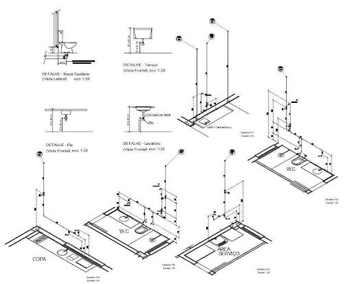
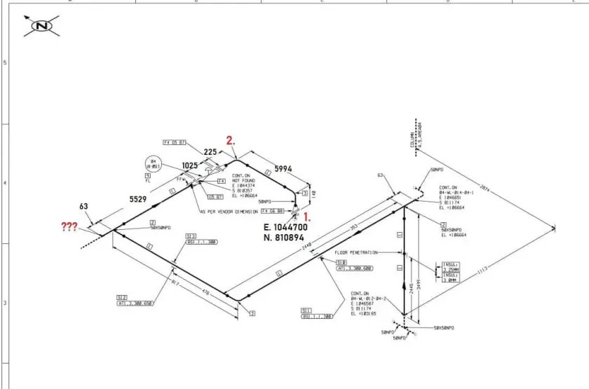
These drawings provide a detailed representation of three-dimensional objects, particularly pertinent to piping systems and their associated symbols.
Isometric drawings present a three-dimensional view of pipelines and their components, offering an unambiguous representation of the system's layout.
In the context of piping symbols, isometrics allow engineers, designers, and technicians to convey the intricate details of a system effectively.
By integrating types of pipeline drawings into their repertoire, professionals can choose the most suitable visual representation method based on the project's requirements.
In industries like Non-destructive Testing (NDT), experts rely on these drawings to assess the integrity of pipelines, identify defects, and plan repairs or maintenance.
The precision of Isometric Drawings ensures that NDT Professionals have an accurate visual guide, which is crucial when dealing with safety-critical systems.
Understanding the Role of Isometric Drawings in the NDT Industry exemplifies their broader significance.
These drawings facilitate seamless communication and problem-solving, ensuring that all stakeholders involved in a project comprehend the design and layout of piping systems.
The world of engineering relies on various visualization techniques, with isometric drawings at the forefront for representing piping systems and symbols.
Their importance in the NDT Industry and beyond cannot be overstated.
However, it's equally vital to appreciate the versatility of other Types of Pipeline Drawings and drawing methods, as they collectively empower professionals to convey complex technical data with clarity and precision.
This comprehensive understanding of visual representation techniques highlights their significance in the modern engineering landscape.
Importance of Isometric Drawings, and their Interpretation
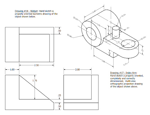
Isometric drawings are a type of pictorial representation used to portray three-dimensional objects on a two-dimensional plane.
These drawings maintain the proportions of all three axes - length, width, and height - without any distortion.
They provide a 3D view of an object in a way that's both easy to understand and construct, making them invaluable in various technical and engineering applications.
The use of isometric drawings in NDT allows for the accurate identification and localization of potential defects.
NDT encompasses a variety of techniques and methods such as Ultrasonic Testing, radiographic testing, magnetic particle testing, and more.
Isometric drawings are used to plan and execute these techniques effectively, ensuring that NDT equipment is applied to the correct locations.
The Importance of Isometric Drawings cannot be overstated, especially in industries like Non-destructive Testing (NDT).
NDT professionals use these drawings as critical visual aids in assessing the integrity of various structures, including pipework.
The precision and clarity of isometrics are essential when identifying defects and planning NDT tests and repairs.
Reading isometric drawings requires an understanding of the conventions used in creating them.
One must recognize the specific angles and grid structure that define the drawing and interpret the symbols and notations representing various components and their relationships within the depicted object.
Isometric drawings often include pipework symbols, which are standardized graphical representations of various elements in piping systems.
These symbols help convey information about pipe connections, valves, fittings, and other components within the system.
Different Types of Isometric Drawing Techniques
Isometric Drawings can be created using multiple techniques, depending on the requirements of their application.
Some of the techniques used include:
- Freehand Drawing:
This technique involves drawing isometric designs or isometric drawings by hand without the aid of specialized tools or software.
Artists or designers with exceptional skills can create isometric drawings freehand.
It requires a good understanding of isometric principles and practice to maintain correct angles and proportions.
- Isometric Grid Paper:
Isometric grid paper is pre-printed with isometric guidelines, including 120-degree angles and equilateral triangles.
Users draw directly on this paper, which simplifies the process of maintaining accurate angles and proportions.
Ideal for beginners and quick sketches, it is a valuable example of isometric drawing.
- Isometric Rulers and Templates:
Isometric rulers and templates are physical tools designed to assist in drawing isometric drawings, isometric designs, and piping symbols for types of pipeline drawings.
They have built-in angles and guidelines for drawing lines and shapes in the correct isometric perspective.
These tools make it easier for individuals to create precise isometric drawings, emphasizing the Importance of Isometric Drawings in engineering and design.
- CAD (Computer-Aided Design) Software:
CAD software, such as AutoCAD and SolidWorks, is widely used for creating isometric drawings, including piping symbols, digitally.
It offers a high degree of precision, with features like snap-to-grid, angle-lock, and automatic scaling.
CAD programs are essential for complex engineering and architectural projects, underscoring the Importance of Isometric Drawings in such fields.
- Online Isometric Drawing Tools:
Various online tools and applications are available for creating isometric drawings without the need for extensive software installations.
These tools often provide templates, grids, and basic drawing functions for isometric projections, demonstrating the versatility of isometric drawing techniques.
- Orthographic to Isometric Conversion:
In cases where orthographic drawings (2D representations) exist, they can be converted to isometric drawings.
This involves redrawing the object using isometric principles, ensuring that it aligns with the 120-degree angles and maintains proportions, showcasing the adaptability of isometric drawing techniques.
- 3D Modeling Software:
3D modeling software, such as Blender or SketchUp, can be used to create 3D models of objects and then generate isometric views from different angles, highlighting the interplay between 3D modeling and isometric drawing.
- Handheld Devices and Stylus Drawing:
Some artists and designers use handheld devices like tablets with stylus pens to create isometric drawings digitally.
Specialized apps and software for these devices offer an intuitive drawing experience, showcasing the integration of modern technology into isometric design.
- Creative Isometric Designs:
In addition to technical drawings, isometric projection is also used for creative art and design, providing an example of an isometric drawing that may not strictly adhere to engineering standards but offers unique and artistic interpretations of three-dimensional space.
Creative isometric designs illustrate the broader scope of isometric drawing techniques.
The technique chosen to create an isometric drawing is highly dependent on available resources, the proficiency of the engineer, level of precision required.
The variety of techniques available makes isometric drawings applicable for multiple applications, hence signifying the relevance of isometric drawings in modern engineering.
How to Draw an Isometric Drawing?
Isometric grid paper comes with pre-drawn equilateral triangles and axes, simplifying the process of creating isometric drawings, including piping symbols and different Types of Pipeline Drawings.
Begin by defining the size and proportions of the object you intend to draw in isometric drawings.
Draw the horizontal, vertical, and depth axes that intersect at the standard 120-degree angles, a key aspect in understanding How to Read Isometric Drawings.
Sketch the edges and outlines of the object, making sure that lines representing edges run parallel to the axes in your isometric drawings.
To represent different components within the drawing, include details, symbols, and labels, vital for conveying information in Isometric Drawings.
- Specialized Drawing Tools:
Use specialized tools like isometric rulers or templates designed for creating isometric drawings and Piping Symbols, which simplify precision work.
These tools provide predefined angles and lines to ensure accuracy in maintaining the isometric projection, contributing to the importance of isometric drawings.
- Digital Software (CAD Programs):
Utilize Computer-Aided Design (CAD) software, such as AutoCAD or SolidWorks, to create isometric drawings digitally, emphasizing the use of technology in isometric drawings.
Begin by configuring the drawing space with the appropriate isometric grid and angle settings, a crucial step when working with CAD programs.
Use the CAD tools to draw lines and shapes with precision, aligning them to the isometric axes.
This modern approach showcases the versatility of isometric drawings.
Take advantage of features like snap-to-grid and angle-lock to maintain the correct angles and proportions.
Add symbols, labels, and annotations as necessary for clarity, contributing to the comprehensibility of Isometric Drawings.
- Maintaining Correct Angles and Proportions:
Regardless of the method chosen, the critical aspect of creating accurate isometric drawings, piping symbols, and different types of pipeline drawings is to maintain the correct angles, typically 120 degrees, and proportions throughout the process.
Pay close attention to the isometric grid to ensure that lines align with the grid lines to maintain the proper angles, a fundamental concept in isometric drawings.
Be mindful of scaling; objects farther from the viewer should appear smaller, while those closer should appear larger, consistent with the isometric perspective. This scaling is a significant aspect of isometric drawings.
The creation of isometric drawings can be achieved through manual methods, specialized tools, or digital software.
The important aspect is to maintain the correct angles and proportions, define the isometric projection, and highlight the importance of isometric drawings, especially in technical fields.
Whether done by hand or with the assistance of tools and technology, this ensures that the resulting drawing accurately represents the three-dimensional object in a two-dimensional format and that individuals can effectively read isometric drawings.
Types of Isometric Drawings
Isometric projection has many types, some of which include:
- Isometric Projection:
This is the most common type of isometric drawing. Here the axes are at equal distances from each other, ideally at a 120-degree angle. Here the proportions of the drawing appear realistic.
- Dimetric Projection:
In dimetric projection, only two of the three axes are equally foreshortened, while the third axis is foreshortened at a different angle.
This type of Pipeline Drawing is not as abundantly used. This highlights certain features of the drawing, as required.
- Trimetric Projection:
Trimetric projection is a variation of isometric drawing where all three axes are unequally foreshortened.
This type allows for the most flexibility in choosing angles for each axis, providing a high degree of customization.
However, it is less standardized than isometric and dimetric projections and is mainly used in specialized applications.
The Three Rules of Isometric Drawing
The three rules of drawing isometric drawings include:
- Isometric Axes:
In isometric drawings, including those featuring piping symbols, it's crucial to maintain the correct alignment of the three axes at 120-degree angles.
This alignment ensures that objects are faithfully represented in their true proportions and sizes, a fundamental aspect of technical drawings.
- Isometric Scale:
The use of the isometric scale, often represented as 1:1, is essential for consistency in Isometric Drawings.
This scale ensures that the foreshortening of each axis is equal, preserving accurate dimensions in both isometric drawings and those involving Types of Pipeline Drawings.
- Isometric Lines:
In Isometric Drawings, the proper orientation of lines is key. Lines parallel to the axes must remain parallel in the drawing.
Furthermore, lines representing edges and outlines of objects in isometric drawings, including those depicting Piping Symbols and various types of pipeline drawings, should maintain a 30-degree angle from the horizontal axis, reflecting the 120-degree angle between the axes.
Adhering to this rule ensures that the details are correctly oriented, resulting in clear and precise technical illustrations.
Understanding these rules and applying them consistently is essential in conveying accurate information in isometric drawings.
This is especially significant in the context of technical drawings that include piping symbols and various Types of Pipeline Drawings, where precision and clarity are paramount.
Conclusion
Technical design and engineering are intricately intertwined with the world of Isometric Drawings.
These specialized drawings offer a profound visual language that transcends traditional two-dimensional representations, enabling the three-dimensional visualization of objects, structures, and systems.
This ability to convey complexity in a clear and comprehensible manner is paramount in the technical field.
Isometric Drawings come in different types, each meticulously designed to serve particular purposes.
The most widely used is isometric projection, characterized by a 120-degree alignment of the three axes.
It is the bedrock of technical drawings, offering a true-to-life portrayal of engineering components, including Piping Symbols and various types of pipeline drawings.
Dimetric projection, with its two equally foreshortened axes and one distinct axis, allows for the emphasis on specific dimensions or features.
The rarer trimetric projection offers unmatched flexibility with unequal foreshortening on all axes but is primarily reserved for specialized applications.
While understanding the various types is crucial, equally vital is mastering the three main rules governing isometric drawings.
The correct alignment of isometric axes, the maintenance of the isometric scale, and the precise use of isometric lines at the prescribed angles are the backbone of any accurate and consistent isometric drawing.
These rules are not just guidelines; they are the language through which clarity and precision are achieved, especially when dealing with Piping Symbols and Types of Pipeline Drawings.
The importance of these rules cannot be overstated in the world of technical illustrations.
Indeed, isometric drawings are indispensable in fields such as engineering, architecture, and design.
They facilitate the seamless transmission of complex ideas, structures, and systems, bridging the visual gap between two and three dimensions.
Mastery of this visual language encompasses not only how to draw isometric drawings but also How to Read Isometric Drawings, a skill set that underlines the significance of isometric drawings in various technical and creative domains.
In a nutshell, Isometric Drawings are the conduit through which technical and creative professionals converse their ideas with clarity and precision.
Through a deep understanding of the techniques and rules associated with Isometric Drawings, individuals unlock the potential of this visual language and make meaningful contributions to the ever-evolving fields of engineering, design, and architecture.
Key Takeaways
- Isometric drawings, including Piping Symbols and various types of pipeline drawings, are vital in technical fields like engineering and design.
- Understanding the three main rules of isometric drawing is essential for precision and clarity in conveying complex concepts and structures.
- Isometric drawings are a powerful visual language that bridges the gap between two-dimensional and three-dimensional representations.
- Mastery of how to draw isometric drawings and How to Read Isometric Drawings enables effective communication in engineering, architecture, and design.


