
Table Of Contents
- Introduction
- What are Pipeline Isometric Drawings?
- ISO Standard Isometrics Symbols
- How to Read Isometric Drawings?
- Non-destructive Testing (NDT): Safeguarding Structural Integrity
- Example of Isometric Drawing: Bridging Theory and Practice
- Conclusion
- Key Takeaways
- FAQs
Introduction
In the world of engineering and construction, communication is key. It's not just about the blueprints; it's about the language those blueprints speak.
One essential dialect in this realm is the language of ISO standard isometric symbols.
There are many types of pipeline drawings in the intricate world of isometric drawings, and they are quite essential for Non-Destructive Testing (NDT) in ensuring the structural integrity of pipelines.
What are Pipeline Isometric Drawings?
Before we dive into the details, let's establish a fundamental understanding of isometric drawings.
These are three-dimensional representations of objects, showcasing a 360-degree view.
When it comes to piping systems, isometric drawings are invaluable.
They provide a comprehensive visual guide, allowing engineers and workers to grasp the intricacies of the pipeline layout.
Pipeline Isometric Drawings are crucial visual representations in the fields of engineering and construction.
These drawings provide a detailed 3D illustration of a piping system, offering a comprehensive view of its components, dimensions, and how they interconnect.
Understanding the intricacies of pipeline isometric drawings is essential for professionals involved in designing, installing, and maintaining piping systems.
The Importance of Isometric Drawings in Piping Design cannot be overstated.
ISO Standard Isometric Symbols
In the realm of pipeline isometric drawings, adherence to ISO standard isometric symbols is paramount.
The International Organization for Standardization (ISO) has established a set of symbols that uniformly represent various elements within a piping system.
These symbols serve as a standardized language, ensuring consistency and clarity in communication among engineers, designers, and other stakeholders involved in the project.
Piping symbols are the alphabet of isometric drawings.
Each symbol carries a specific meaning, akin to words in a language.
Understanding these symbols is crucial for anyone involved in the construction and maintenance of pipelines.
From valves to pumps, each element has its unique representation in the isometric language.

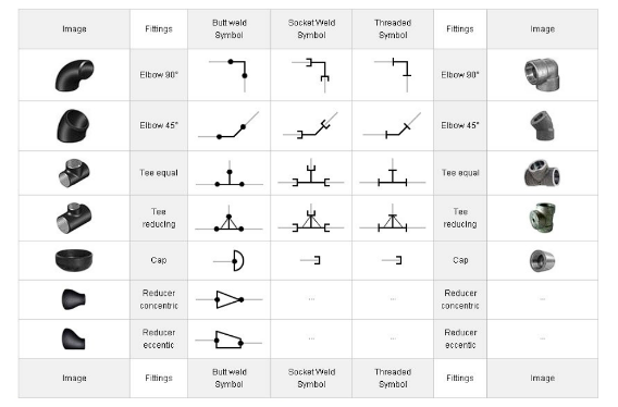
- Fittings
Fittings are integral components in Pipeline Isometric Drawings, playing a pivotal role in connecting and redirecting pipes.
These include elbows, tees, reducers, and couplings. In accordance with ISO standards, each fitting has a unique symbol.
Understanding these symbols is crucial for accurately interpreting the drawing and ensuring seamless integration of fittings within the overall piping system.
- Flanges
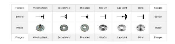
Flanges are essential for connecting pipes, valves, and other equipment.
Standardized symbols designating the type and specifications of flanges appear in pipeline isometric drawings.
The accurate depiction of flanges is vital for ensuring proper alignment and connection between different segments of the piping system.
- Valves
Valves are critical control elements in a piping system, regulating the flow of fluids.
In Pipeline Isometric Drawings, valves are depicted using ISO standard symbols that convey their type, function, and operation.
Engineers and technicians rely on these symbols to identify and understand the role of valves within the larger context of the piping infrastructure.
- Special Components
Beyond standard fittings, flanges, and valves, pipeline isometric drawings may include special components based on the unique requirements of a project.
These could encompass specialized instruments, control devices, or custom-designed elements.
The depiction of these unique components adheres to the precise symbols set forth by ISO standards, ensuring a thorough and accurate representation within the drawing.
How to Read Isometric Drawings?
Reading isometric drawings may seem like deciphering a secret code, but fear not! We're here to guide you through the process.
From grasping the scale to interpreting symbols, we'll cover the essentials to ensure you can navigate through isometric drawings with confidence.
Not all pipelines are created equal, and neither are their drawings.
From orthographic projections to 3D models, each type serves a unique purpose in the world of Pipeline Design.
Non-Destructive Testing (NDT): Safeguarding Structural Integrity
In the realm of pipelines, structural integrity is non-negotiable.
The NDT Method emerged as the superhero, ensuring the soundness of pipelines without compromising their structure.
Selecting the appropriate NDT method is crucial for accurate results.
Isometric designs are characterized by their use of three-dimensional perspective, which adds depth and dimension to the overall composition.
This combination of form and function allows for a seamless integration of practicality and beauty, resulting in designs that not only serve their intended purpose but also captivate the viewer's eye.
Example of Isometric Drawing: Bridging Theory and Practice
To cement our understanding, let's walk through an example of an isometric drawing.
This practical illustration will connect the theoretical knowledge we've gained with its real-world application, providing a holistic view of the isometric drawing process.
Imagine we are tasked with creating an isometric drawing of a simple house.
We would start by sketching the basic outline of the house, ensuring that all three dimensions are represented accurately.
Then, we would add in details such as windows, doors, and roofs, using the isometric grid as a guide to maintain the correct perspective.
This hands-on exercise will help solidify our understanding of isometric drawing and its practical uses in various industries, such as architecture and engineering.
Conclusion
The world of ISO-standard isometric symbols is a rich and intricate tapestry.
Isometric drawings, piping symbols, and Non-destructive Testing are the pillars of this world, ensuring that pipelines stand tall and strong.
Understanding the intricacies of Pipeline Isometric Drawings, including ISO standard isometric symbols, fittings, flanges, valves, and special components, is foundational for professionals in the field.
The use of standardized symbols enhances communication and collaboration across diverse teams involved in the design, construction, and maintenance of piping systems.
In the subsequent sections, we will delve deeper into each of these components, shedding light on their significance and role in the realm of pipeline engineering.
Isometric symbols have evolved from historical origins to become a vital language in visual representation.
Their applications span design, architecture, engineering, gaming, art, and more.
As we move forward, the enduring relevance of isometric symbols is evident in their adaptability and effectiveness in conveying complex information.
Key Takeaways
- Effective communication in engineering and construction goes beyond blueprints; it involves understanding the ISO standard isometric symbols.
- Pipeline isometric drawings provide a 3D representation of piping systems, offering a comprehensive view of components, dimensions, and connections.
- Adherence to ISO standard isometric symbols is crucial for representing various elements within a piping system.
- Piping symbols serve as the alphabet of isometric drawings, with each symbol representing a specific component, similar to words in a language.
- Fittings, flanges, and valves play essential roles in pipeline isometric drawings, each with unique symbols according to ISO standards.
- Unique project requirements may lead to the inclusion of special components in isometric drawings, with their depictions following precise ISO symbols.
- Reading isometric drawings involves understanding scale, interpreting symbols, and navigating through different types of pipelines.
- NDT methods are crucial for ensuring the structural integrity of pipelines without compromising their design.
- Isometric designs use a three-dimensional perspective, adding depth and dimension.
FAQs
Q. What is ISO in isometric drawing?
A: In the isometric drawing, "ISO" typically refers to the International Organization for Standardization, but in the context of isometric drawing, it might also refer to the term "isometric."
Isometric drawing is a type of pictorial representation of three-dimensional objects in which all three dimensions are drawn at the same scale and the angles between the axes are 120 degrees.
Q. What is the standard isometric drawing?
A: There isn't a single "standard" isometric drawing, as different industries and applications may have variations.
However, a commonly used standard for isometric drawings is the one where the three principal axes form equal angles of 120 degrees with each other.
This provides a balanced and visually clear representation of three-dimensional objects.
Q. What is the full form of an ISO drawing?
A: The term "ISO" in the context of drawing usually refers to the International Organization for Standardization.
However, in the context of isometric drawing, it doesn't have a specific full form.
"Isometric" is derived from the Greek words "isos" (equal) and "metria" (measuring), indicating that the scale along each axis is the same.
Q. What are the three views of isometric drawing?
A: The three views in an isometric drawing represent the object from three different angles. These views are:
- Isometric Top View: It shows the top surface of the object.
- Isometric Left-Side View: It shows the left side of the object.
- Isometric Right-Side View: It shows the right side of the object.
Q. Why is the isometric angle 30?
A: The isometric angle is 30 degrees because it provides a visually balanced representation of three-dimensional objects.
This angle maintains equal spacing between the three axes (x, y, and z) and ensures that the scale along each axis is the same.
A 30-degree isometric projection is widely used in engineering and technical drawings as it simplifies measurements and calculations while offering a clear depiction of the object's form.


