
Table of Content
- History of Pipeline Drawing
- What is Pipeline Drawing? How is it used in NDT?
- How to draw a Pipeline Drawing?
- What are the different types of Pipeline Drawings?
- Pre-Requisites For Checking The Pipeline Isometric
- How to Read Isometric Drawings?
- Methodology of Drawing Pipeline Isometric Drawings
- How to Draw Isometric Drawings?
- ISO Standard for Symbols
- Importance of Accurate Pipeline Drawings
- Sectional Views In Isometric Drawings
- What is hatching in Isometric Drawings?
- What is a Compound Angle?
- Importance of Labelling in Isometric Drawings
- Healthy Pipeline Isometric Drawings Dimensioning Practices
After a black ‘n’ blue Monday, I completely understand how tiresome it must be to examine those Pipeline 2D isometric drawings, let alone interpret them. To give you a sigh of relief, here’s the brief and accurate information you need to understand your complex isometric drawings. Also, count on this blog to gain the knowledge to create one, in case you need it!
On the count of 3, 2, 1, let's dive into the blog...
History of Pipeline Drawing
Pipeline drawings have evolved exponentially throughout history, originating in ancient civilizations with primitive sketches and diagrams used for water supply systems and aqueducts. However, it was during the industrial revolution in the 18th and 19th centuries that the formalization and standardization of pipeline drawings began. The expansion of the railroad and oil industries highlighted the need for accurate pipeline documentation, leading to the development of more sophisticated and detailed pipeline drawings. The introduction of mechanical drawing techniques and standardized symbols improved communication among engineers, making pipeline designs more comprehensible. In the mid-20th century, the advancement of computer-aided design (CAD) technology revolutionized the pipeline drawing process. CAD software enabled engineers to create digital representations of pipelines with unparalleled precision and efficiency.
As the 20th century progressed, CAD software continued to improve, solidifying pipeline drawings as indispensable tools in pipeline planning, construction, and maintenance projects. Moreover, the integration of Geographic Information System (GIS) technology further enhanced pipeline drawings by providing spatial accuracy and georeferenced representations of pipeline networks. Accurate and up-to-date pipeline drawings play a pivotal role in enhancing efficiency, safety, and regulatory compliance within the industry, whether for designing new pipelines or inspecting existing ones.
Today, pipeline drawings play a pivotal role in various industries, ensuring the safe and efficient transportation of fluids and gases while adhering to stringent regulatory standards. They have become indispensable assets for designing, constructing, and managing complex pipeline systems.
What is Pipeline Drawing? How is it used in NDT?
Comprehending Non-destructive Testing pipeline drawings is of utmost importance for NDT inspectors and engineers responsible for inspecting, maintaining, and evaluating the integrity of pipeline systems. These drawings offer vital insights into the pipeline's arrangement, measurements, materials, inspection points, and other relevant particulars. Some of the essential factors to consider while interpreting Pipeline drawings in NDT include:
- Interpreting Symbols and Annotations
NDT pipeline drawings often include specific symbols and annotations to indicate inspection points, recommended NDT Methods, and known defects or anomalies. Familiarity with these symbols is vital for planning inspections and pinpointing areas of concern.
- Analyzing Pipeline Components
Pay close attention to how various pipeline components, such as valves, flanges, fittings, and joints, are represented. Understanding their type and location helps inspectors target specific areas during inspections.
- Noting Material Specifications
The drawings usually specify the type of material used for constructing the pipeline. Different materials may necessitate distinct NDT Techniques, making it crucial to choose appropriate inspection methods.
- Understanding Pipeline Dimensions
Thoroughly review the dimensions provided on the drawings, including pipe diameter, wall thickness, and overall length. Precise measurements are critical for selecting suitable NDT Equipment and ensuring comprehensive inspection coverage.
- Identifying Branches and Connections
Locate branches, connections, and intersections in the pipeline system. These areas often serve as critical points for potential defects, warranting prioritized inspections.
- Verifying As-Built Drawings
Confirm that the pipeline drawings represent the actual configuration after construction or modifications. Using the most up-to-date drawings ensures accurate inspections.
- Integrating with P&ID
If available, integrate pipeline drawings with the P&ID (Piping and Instrumentation Diagram). This integration provides a comprehensive understanding of the entire pipeline system, including valves, pumps, and associated equipment.
- Considering Spatial Coordinates
For complex pipelines, drawings may include spatial coordinates. These coordinates assist in precisely positioning NDT inspection tools.
- Factoring Service Conditions
Understand the pipeline's service conditions, such as transported material, pressure, and temperature. This knowledge aids in selecting NDT Methods effective for detecting defects under these conditions.
- Adhering to Regulatory Compliance
Ensure that the pipeline drawings comply with relevant industry standards and regulatory requirements for inspections and maintenance.
Inspectors must be well-versed in engineering and pipeline terminology, NDT Methods, and industry best practices to make effective use of NDT pipeline drawings. Regular communication with engineers and stakeholders engaged in the pipeline project is crucial as it helps clarify any uncertainties and ensures inspections are carried out efficiently and safely.

How to draw a Pipeline Drawing?
Creating pipeline drawings is a critical process that involves accurately depicting the layout and particulars of a pipeline system. These drawings serve as crucial means of communication for engineers, designers, and stakeholders engaged in pipeline construction, maintenance, and inspection. Here's a general outline of the steps involved in creating pipeline drawings:
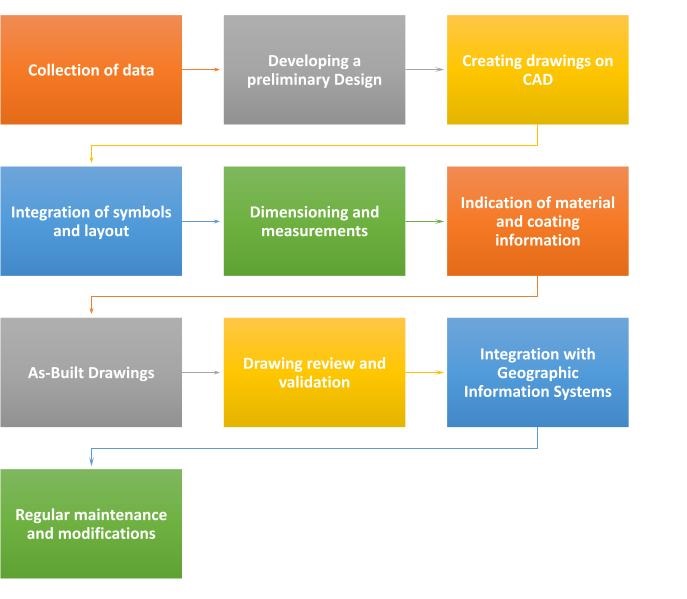
- Collection of data
The initial step is collecting relevant data about the pipeline project, including details about the pipeline route, dimensions, materials, components, and other pertinent information. Existing survey data, engineering specifications, and as-built plans serve as valuable sources.
- Developing a preliminary design
Based on the collected data, engineers and designers develop a preliminary design of the pipeline system. This design outlines the pipeline route, connections, and vital components, serving as a starting point for the pipeline drawings.
- Creating drawings on CAD
Modern pipeline drawings are typically created using Computer-Aided Design (CAD) software. Pipeline drawing software such as these offers various features that allow for precise and efficient drafting of pipeline layouts. The software enables the creation of both two-dimensional (2D) and three-dimensional (3D) representations of the pipeline.
- Integration of symbols and layout
Engineers utilize CAD software to draw the pipeline layout, encompassing straight sections, bends, and junctions. Standardized symbols and annotations are added to represent valves, fittings, pumps, and other components.
- Dimensioning and Measurements
Accurate dimensions and measurements are of utmost importance for pipeline drawings. The CAD software enables engineers to specify the length, diameter, and wall thickness of different pipeline segments.
- Indication of material and coating information
The drawings should indicate the materials used for constructing the pipeline, as well as any coatings or linings applied to protect against corrosion.
- As-Built Drawings
As the pipeline construction progresses, as-built drawings are updated to reflect the actual configuration of the pipeline. These drawings serve as a record of the final installation.
- Drawing review and validation
Once the initial pipeline drawings are complete, they undergo a rigorous review process by engineers and stakeholders to ensure accuracy and compliance with project requirements.
- Integration with Geographic Information Systems
For more complex projects, the pipeline drawings may be integrated with GIS data, providing additional spatial context and information.
- Regular maintenance and modifications
Regular maintenance and updates of pipeline drawings are essential to reflect any updates, repairs, or changes made to the pipeline system over time.
Creating pipeline drawings demands technical expertise, attention to detail, and the use of advanced CAD tools. The accuracy and comprehensiveness of these drawings are crucial for successful pipeline planning, construction, and safe operation
What are the different types of Pipeline Drawings?
In Non-destructive Testing (NDT), several types of pipeline drawings are used to facilitate inspections, assessments, and maintenance of pipeline systems. These drawings provide valuable information about the pipeline's layout, dimensions, materials, and inspection points. Some of the common types of Pipeline Drawings in NDT include:
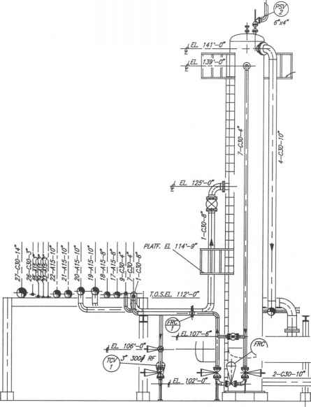
Isometric Drawings
Isometric drawings are three-dimensional representations of pipeline sections that show the angles and bends in the pipeline. These drawings are particularly useful for understanding how the pipeline moves through space, which helps in planning inspections in complex or tight areas.
Plan-View Drawings
Plan-view drawings provide a top-down view of the pipeline layout. These drawings give inspectors an overview of the pipeline's route, including its start and end points, branches, and connections. Plan-view drawings are crucial for identifying the locations of inspection points and potential areas of concern.
Elevation Drawings
Elevation drawings display a side view of the pipeline. This type of drawing helps inspectors visualize the pipeline's height and how it interacts with the surrounding environment. Elevation drawings can be essential when planning inspections in areas with varying ground levels or while assessing the pipeline's alignment with other structures.
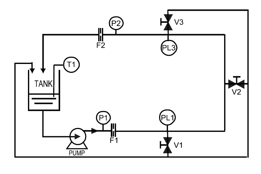
Schematic Diagrams
Schematic diagrams are simplified and abstract representations of the pipeline system. These drawings use symbols and lines to depict the components and flow paths. Schematic diagrams are often used to provide a clear, easy-to-understand overview of the pipeline and its key features.
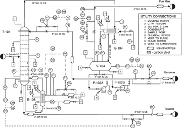
Piping and Instrumentation Diagram (P&ID)
P&ID drawings depict the interconnections of piping, equipment, and instrumentation within a processing facility or plant. These drawings are not specific to a single pipeline but provide a comprehensive overview of the entire system, allowing inspectors to understand how different components work together.
As-Built Drawings
As-built drawings are updated versions of the original pipeline drawings that reflect the actual configuration of the pipeline after construction or modifications. These drawings are essential for tracking changes over time and ensuring that inspections are conducted on the most current pipeline layout.
Cross-Sectional Drawings
Cross-sectional drawings show a cutaway view of the pipeline, revealing its internal structure and components. These drawings help understand the thickness of the pipe walls and identify potential issues like corrosion or defects.
Each type of piping drawing serves a specific purpose and provides valuable information for NDT inspections. By using a combination of these drawings, NDT inspectors can effectively plan and conduct inspections, assess the pipeline's integrity, and ensure the safe operation of the pipeline system.
Read in detailed - Types of Pipeline Drawing
Pre-Requisites For Checking The Pipeline Isometric
Certain documents are essential for creating, studying, and recording pipeline structures. Pipeline isometric drawings are not issued for utilization unless approved and issued an IFC (Issued for construction) certificate. Inaccuracies in the drawings can cause catastrophic losses to the organization regarding time, labor, money, and resources. The documents are as follows:
- Pipeline and Instrument Diagrams (P&ID documents)
This encompasses data about additional instruments, insulation data, and line data.
- Line list:
This carries vital data about temperature and pressure, stress zones, water pressure, class of inspection, etc.
- General Arrangement Drawing (GAD)
This document holds orientation, lines, dimensions, and part location data.
- Piping Material Specifications
This document contains extensive data about materials used in the pipeline structure.
- Equipment Drawing
This document provides data on connections in the pipeline.
- Orientation of Nozzle
Nozzle installment requires careful consideration of the angle of orientation and the elevation of the nozzle.
- Piping Support Drawing
The supports required for the pipeline structure require carefully considered allotment. This document carries the data required for it.
- Special Items Detail
The special additions and parts required in the pipeline structure are logged in this document, along with in-depth material details, load details, and dimensioning data.
- Instrument Installation Data
This document contains end users' installation requirements and connector details.
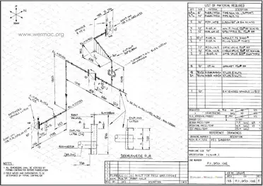
How to Read Isometric Drawings?
Pipeline Isometric Drawings have certain compulsory components that aid the user in analyzing the otherwise complex pipeline isometric document. These common components are as follows:
1. Title Block
The title block should have the following data to ensure thorough communication of the pipeline structures:
- Drawing Number
- Line Numbers
- Sheet Data
- Pipeline and Instrumentation Data
- General Arrangement and Layout
- Project Details include the Project name, project number, project code, and area code.
- In the case of insulation in the systems, the type of insulation should be mentioned.
- Pipeline Testing Data
- Class of inspection
- Pressure data for the fluid that the pipeline is designed for.
- Pressure and Temperature of the pipeline design.
2. Isometric Drawing Area
- Isometric drawing
- Name and location of the pipeline equipment
- Coordinates for all components
- Nozzle orientation data
- Dimensional data of nozzles
- Direction and allotted angles
- Elevation of the nozzle using the center axis
- Elevations of the base of structures
- Axis orientation, offset, and location.
- Slope involved in the installation, if any.
- Specifications and line details
- Breaks in specifications, if any.
- Dimensional data is involved in the structure.
- Drawing numbers of continued drawings if the structure drawing spans multiple pages.
- Locations of individual instruments and their components.
- Location and structures of control valves
- Location of grids
- Data on special items
- Requirements of orifice meters
- Ventilation and drainage details and location
- Weld data for manufacturing of components
- Weld data for installation
- Size of branches
- Size of reducers
- Gap data for welds
- Sequencing of components
- Orientation of taps and the direction of flow of fluid to be carried in the pipes.
3. Bill of Materials (BOM)
- Description of individual structural elements
- Quantities of elements involved in the drawing.
- Materials that the individual components are made of.
- Variety and quantity of valves
- Size and manufacturing rating of components
- Industry codes followed by the pipeline structure
- Special components, instruments, and such data must be logged in the Bill of Materials.
- Length of structure and its dimensions
- Quantity and variety of structural supporting elements
4. Notes section
This section contains data on any specific requirements and additional components. This varies from project to project, and this section can be completely skipped if there is no data to provide. It contains the following data:
- Data related to the slope and orientation of the structure should be mentioned in the presence of any such special situations.
- In case the fluid to be carried in the pipeline is specific i.e., corrosive, edible, etc. Unique requirements and related data should be mentioned.
- Piping and Instrumentation distance, lengths, and pressure can be mentioned in this section.
- Requirements for unhindered uninstallation and dismantling of the structure can also be mentioned here.
Methodology of Drawing Pipeline Isometric Drawings
Scale
Pipeline isometric generally depicts a large-scale pipeline structure and is never drawn to scale. It should be noted, however, that the dimensioning in the drawings, despite the scaling down is always in proportion. The steps involved henceforth include:
- Creation of a sample isometric diagram prototype wherein the plane orientation, title blocks, BOM, dimensioning data, snap, and grid are pre-set.
- Create a library of the isometric symbols involved, including any additional parts, fittings, valves, etc., that are significant to the drawing.
- Dimensioning should be created for all isometric planes.
- A list and menus for easy access to symbols should be created.
How to Draw Isometric Drawings?
The process of drafting isometric drawings for a pipeline system involves referencing the arrangements of the pipelines, sections, and elevation drawings during its development.
Accurate drawing symbols, callouts, precise coordinates, and elevations provide intricate information to the fabricator.
Isometric symbols corresponding to their Orthographic equivalents help the drafter relay elaborate specifications about the routing of the pipelines.
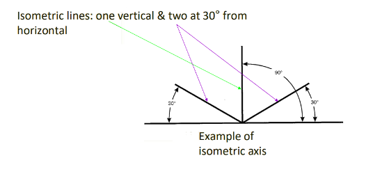
- It is possible to measure the Above isometric lines.
- Lines not parallel to the isometric lines in the orthographic plane cannot be measured.
As stated in the above example, the pipes in the drawing all lie along the directions of the three isometric axis lines.
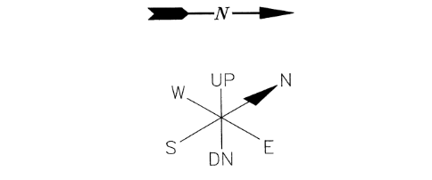
Location and Direction:
The location and direction of the lines in the drawing can determine the orientation of the pipelines.
An arrow pointing towards the north in the upper right side of the diagram helps with the orientation.
- Location-providing structural points are drawn in the isometric drawings.
- Indicating the dimensions for the reference points is compulsory, i.e., Existing equipment, structures, etc.
- Isometric drawings involve marking the coordinates of the scaled-down pipe system.
Fitting Symbols And Orientation
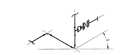
For the orientation of the fittings and valves, it is recommended they are drawn parallel to the last change in direction or branching in the pipeline, as shown in the image :
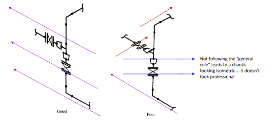
Recommend technique for Fitting symbols and valve orientation (image credits: "Pipe drafting and design”- Second edition)
- Fittings with shapes taken from the plans and elevation drawings are drawn at an isometric angle.
- Elbows are drawn depending on the industry standard as stated below:
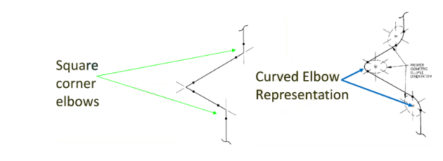
Different ways Elbows are drawn (Image credits: "”- Second edition)
ISO Standard for Symbols
- Fittings
These components are pieces of pipe fabricated according to the thickness of the pipe wall, are used to Branch out from a main pipe (tee), make changes in direction (elbow), or reduce the size of the line (reducer).
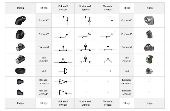
ISO symbols for different Fittings (Image credits: Pipe drafting and design”- Second edition)
- Flanges
These components are ring-shaped contraptions used as a substitution for threading or welding various piping components through the pipeline system. Unlike welded connections, they are more reliable than threaded joints and can be inspected and disassembled.
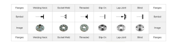
ISO Symbols for Different Flanges (Image credits: Pipe drafting and design”- Second edition)
- Valves
These devices’ primary function is to regulate the flow and change the volume, pressure, and rates at which the fluids flow through the pipeline, insuring no backward flow during structural failure.


ISO Symbols for Different Valves (Image credits: “Pipe drafting and design”- Second edition)
- Special Components
Specific applications require specialized components for usage that come in a variety of forms to carry out multiple functions of the above-stated components, as shown below:


ISO Symbols for Various Special Components (Image credits: “Pipe drafting and design”- Second edition)
Importance of Accurate Pipeline Drawings
Accurate pipeline drawings are important in the field of non-destructive testing for the following reasons:
- Inspection Planning
- Efficient Testing
- Targeting Deformities and Anomalies
- Identifying Defects
- Safety Compliance
- Asset Management
- Communication and Collaboration
- Decision-making
- Risk Assessment
Sectional Views In Isometric Drawings
Sectional Views refer to a complete or partially sectioned view of the pipeline isometric drawings. This sectioned view gives information about the interiors of the pipeline design, which are not observable on the surface.


Sectioned orthographic and Isometric views (Image credits: Engineering Drawing - EPHTI 2005) To better draw sectional views, the following terminology is important to understand.
- Cutting Plane Lines
These lines indicate an imaginary plane sectioning through the structure, which can be easier to imagine with a proverbial saw-blade hacking through a structure.
This sectioning is represented by black dotted lines as shown in the figure:

Cutting Plane lines (Image credits: Engineering drawing -EPHTI 2005)
- The Direction of Sight
The direction in which the observer views the object after the sectioning has been indicated by the drafter as a small arrow, as shown in the diagram:

The direction of the site (Image credits: Engineering drawing -EPHTI 2005)
- Section Lining
A thin black line is drawn at 45 degrees to the horizontal, showing where the structure has undergone sectioning. They are uniform in thickness and evenly spaced with the human eye, as represented below:

Section Lining (Image credits:: Engineering drawing -EPHTI 2005)
- Full-Section View
Involves a section of one of the multi-views of the drawing sliced or completely sectioned in halves.

Full-section View (Image credits: Engineering Drawing - EPHTI 2005)
- Offset section View
This involves sectioning the view in an offset plane or bending the cutting plane line to observe interiors not present in a straight line.

- Half Section View
This View involves half of the section of the drawing to be viewed; section-lining or cross-hatching is used to indicate the sectioning.

Half Section View (Image credits: Engineering Drawing - EPHTI 2005)
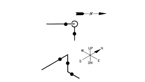
What is hatching in Isometric Drawings?
Hatching is used in isometric drawings to indicate any inclination in the pipeline, spacing the angle again the direction in the pipe runs. Conventionally the pipe would be assumed to be running up and then moving east. Still, the example shows otherwise as the hatching indicates the pipeline is moving north as stated in the below diagram(Fig: a,b):


What is a Compound Angle?
If the piping must pass through other equipment, the isometric drawing contains data regarding the offset and rolling. These two factors combined produce a compound angle. The compound angle data is a vital factor in understanding pipeline isometrics and consists of four main factors that are:
- Run: This factor is the length of the offset pipe drawing, calculated in the direction of offset of the pipeline.
- Set: This provides the offset depth from start to finish.
- Roll: This provides the breadth of the offset.
- Travel: This is the actual length of the pipe through the offset zone.
Importance of Labelling in Isometric Drawings
The basic guidelines for labelling pipeline isometric drawings are:
- In the documentation of vertical pipelines, the lettering should be vertically documented and at an angle of 30° (stated in the earlier sections)
- In the case of horizontal pipelines, the dimensions appear to lay at a 30° angle.
- Dimensions appear to lay down in the case of horizontal dimensioning and appear straight in the vertical dimensioning of the pipe.
Healthy Pipeline Isometric Drawings Dimensioning Practices
- A center axis should be created at a juncture point in the drawing, and all dimensioning data should be marked concerning that point.
- The pipeline isometric drawing should be avoided during dimensioning, and all dimensioning data should be marked outside the drawing zone.]
- Dimensioning of specific elements should only be carried forward between points in the same plane.
- A dimensioning line should be extended to be produced as the center line for the run of the pipeline drawing.
- It should be ensured that any text mentioned vertically in the drawing should be parallel with extension lines connecting the dimensions to the center line.


