Table Of Content
- What is Remote Field Testing (RFT)?
- The Principle of Remote Field Testing: Through-Transmission
- Transmitter and Receiver Coils
- The Two Coupling Paths
- Direct Path
- Indirect (Remote) Path
- Why the Field Crosses the Wall Twice
- Reading Wall Loss by Phase and Amplitude
- Phase
- Amplitude
- RFT Probes and Equipment
- Applications of Remote Field Testing
- Where RFT Fits: RFT vs ECT, NFT and IRIS
- When to Choose RFT
- When Another Method May Be Better
- Limitations of Remote Field Testing
- Conclusion
- Frequently Asked Questions (FAQs)
What is Remote Field Testing (RFT)?
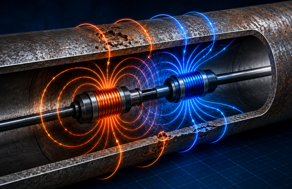
Remote Field Testing (RFT) is an electromagnetic non-destructive testing (NDT) method used mainly to examine ferromagnetic pipes and tubes. In RFT the magnetic field passes through the tube wall twice before it is measured, which gives it near-equal sensitivity to defects on the inside diameter (ID) and outside diameter (OD) of the tube. That balance is precisely what conventional eddy current testing cannot offer, since conventional ECT is heavily biased toward the surface nearest the probe.
This capability makes RFT one of the most dependable methods for evaluating carbon steel heat exchanger tubes, boiler tubes, feedwater heaters, pipelines and cast iron water mains.
The Principle of Remote Field Testing: Through-Transmission
The key feature of remote field eddy current testing is through-transmission. Conventional eddy current testing relies on electromagnetic fields that stay near the probe, whereas remote field testing measures a magnetic field that has crossed the tube wall twice before reaching the receiver.
Two design decisions make this possible.
The first is frequency. RFT operates far below conventional eddy current frequencies, typically in the range of tens to a few hundred hertz, and lower still for thick-walled cast iron. The reason is magnetic permeability. Carbon steel is permeable enough to compress eddy currents into a very thin surface layer at normal ECT frequencies, so RFT drops the frequency until the field can penetrate the wall at all.
The second is coil separation, covered below. Together these give RFT both internal and external defect sensitivity at the same time.
Transmitter and Receiver Coils
An RFT inspection probe consists of:
- A transmitter, also called the exciter or driver coil
- One or more receiver coils
- A centering device that holds the probe body near the tube axis
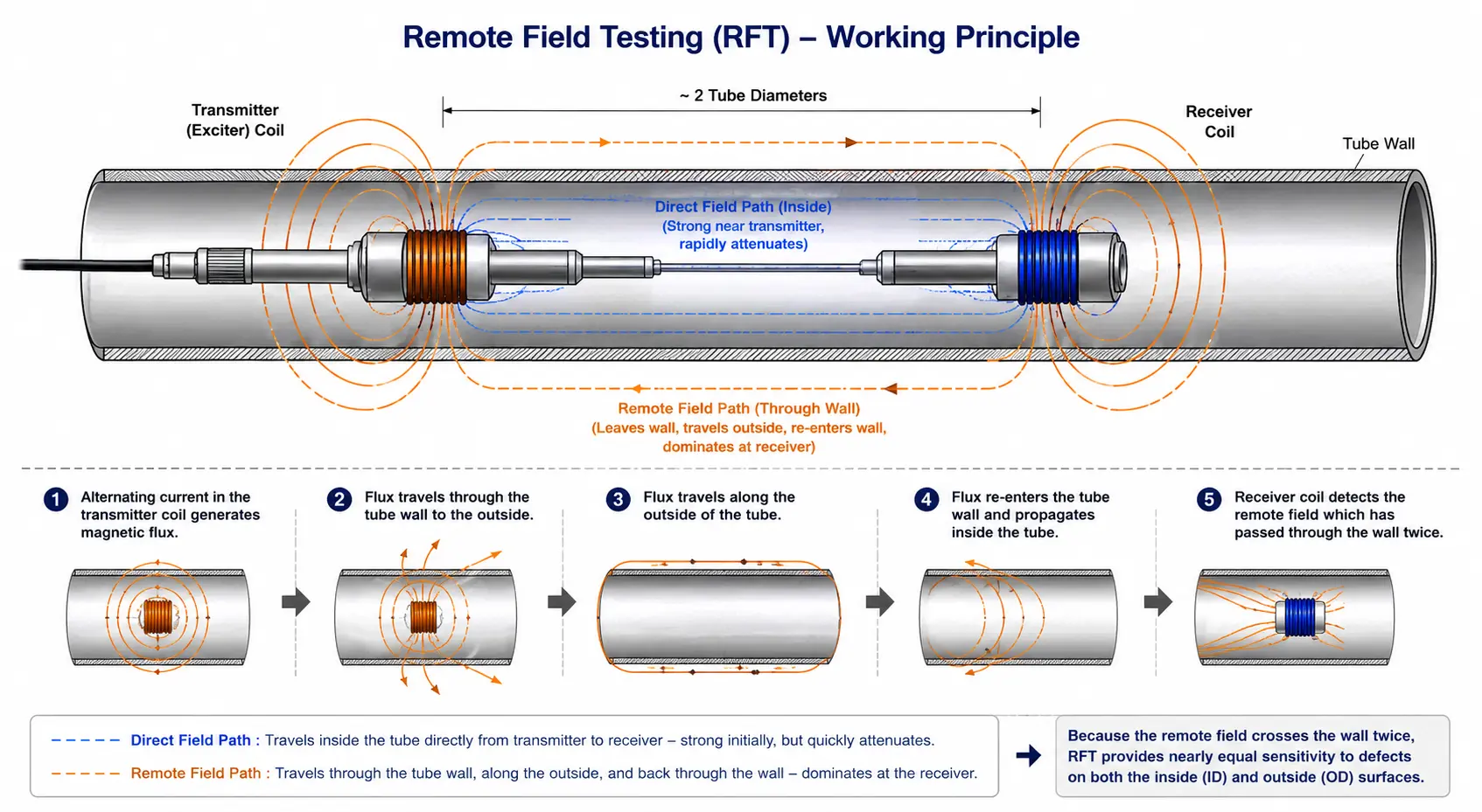
In remote field testing the receiver coil sits about two tube diameters from the transmitter coil, rather than using two closely spaced coils as conventional ECT does.
That spacing matters. Closer than roughly one and a half diameters, the direct field still dominates and the probe behaves more like a conventional eddy current probe. This in-between region is known as the transition zone. Past about two diameters the direct field has decayed sufficiently that the receiver picks up the weak remote field instead, and that is where it belongs.
The Two Coupling Paths
When a low-frequency alternating current is driven through the exciter coil, the magnetic field reaches the receiver by two different routes.
Direct Path
The first is the obvious route, straight down the bore from transmitter to receiver. Close to the transmitter this field is very strong.
It does not stay that way. Carbon steel has high magnetic permeability and reasonable electrical conductivity, so the direct field is rapidly attenuated by eddy current losses, magnetic absorption and the skin effect. Within a short axial distance it has faded to almost nothing.
Indirect (Remote) Path
The second route is quite different. Rather than staying inside the tube, this part of the field:
- Crosses the tube wall from the inside out, near the transmitter
- Travels axially along the outside of the tube wall
- Crosses back through the wall from the outside in
- Couples into the receiver coil
Because this field has passed through the wall twice, it carries information about the condition of the tube from both sides. At the receiver location it is stronger than the direct field, and that region is what gives remote field testing its name.
Why the Field Crosses the Wall Twice
The double wall crossing is what most clearly separates RFT from other electromagnetic tube testing methods.
In the course of transmission, the magnetic field crosses the wall on leaving the tube, travels along the outside, and crosses the wall again before it reaches the receiver.
Each crossing adds phase lag, and the amount of lag depends on how much metal the field had to get through. Two crossings means roughly twice the phase lag of a single crossing, which makes the measurement sensitive to wall thickness.
More importantly, the field does not care which surface the metal is missing from. Wall loss on the internal surface and wall loss on the external surface both reduce the amount of material the field crosses, and both produce a broadly similar response. There is far less inner surface bias than in conventional eddy current testing.
RFT is well suited to detecting:
- External corrosion
- Internal corrosion
- General wall thinning
- Erosion
- Pitting
- Baffle wear
Reading Wall Loss by phase and amplitude
RFT measures two attributes of the received signal.
Phase
Phase lag depends on the thickness of the wall. As a wall corrodes or erodes and thins, the field undergoes less phase lag crossing it, and that shift is what sizing is based on. The relationship is stable across a useful range, which is why phase is generally recognized as the best parameter for sizing gradual wall loss.
Amplitude
Signal amplitude responds to how abrupt and localized a defect is. Pits, grooves and severe corrosion produce measurable amplitude changes even where their effect on average wall thickness is modest. Amplitude is therefore most useful for identifying isolated defects and for confirming indications already seen in the phase data.
Modern inspection software combines both measurements to improve defect characterization and reduce false calls. Neither one alone is enough.
RFT Probes and Equipment
A typical remote field eddy current testing system consists of:
- Instrument
- Exciter (driver) coil
- Receiver coil or coils
- Probe centering device
- Data acquisition software
Systems can be configured with single-driver probes for standard tube inspection, double-driver probes for better signal in difficult conditions, and array configurations for covering large assets faster.
One advantage of RFT over conventional eddy current inspection is that it is relatively insensitive to variations in fill factor. A probe that does not fit the tube snugly will still produce usable data, which helps when a bundle contains tubes at slightly different internal diameters or with varying deposit thickness.
Tolerant is not the same as indifferent, though. Probe centering still matters, which is why a centering device appears in the equipment list above. An off-center probe produces asymmetric coupling and can generate indications that look like real wall loss.
A detailed discussion of probe design, array technology and Remote Field Array (RFA) systems is beyond the scope of this article and is better covered separately.
Remote Field Array (RFA) extends conventional remote field testing by combining array technology with RFT for improved defect characterization and faster ferrous tube inspections.
→ Read: Remote-Field Array (RFA) Technology for Ferrous Tubing Inspections
Applications of Remote Field Testing
The ability to inspect ferromagnetic materials is why remote field testing is used so widely across power generation, petrochemical, water distribution and manufacturing.
Typical inspection targets include:
- Carbon steel heat exchanger tubes
- Boiler tubes
- Feedwater heater tubes
- Ferromagnetic condenser tubing
- Carbon steel pipelines
- Cast iron water mains
- Ductile iron pipelines
- Industrial process tubing
Common flaws found include general wall loss, internal corrosion, external corrosion, pitting, erosion, flow-accelerated corrosion, baffle plate wear, localized metal loss and manufacturing variations in wall thickness.
Since the inspection covers both the external and internal surfaces of the tube, RFT is frequently chosen where external corrosion is present but not visually accessible. A tube bundle in service gives you access to the bore and nothing else, so damage on the outside surface or in the shell-side flow path is invisible to internal visual inspection and largely invisible to conventional eddy current testing.
Learn how Remote Field Array technology is used to detect corrosion and wall loss in large ferrous pipes, extending the capabilities of conventional remote field testing.
→ Read: Corrosion Detection in Large Ferrous Pipes – Remote Field Array Technology
Where RFT Fits: RFT vs ECT, NFT and IRIS
Selecting the correct inspection technique depends on tube material, expected damage mechanism, accessibility and inspection objectives.
When to Choose RFT
Choose remote field testing when inspecting carbon steel or other ferromagnetic tubes and both internal and external corrosion are a concern. RFT is especially useful for detecting overall thinning and corrosion underneath support structures or baffle plates.
When Another Method May Be Better
Where the material is non-ferromagnetic, such as austenitic stainless or copper alloys, and small cracks are the target, conventional ECT remains the preferred choice. Note that ferritic and duplex stainless are ferromagnetic despite the name, so check the actual grade rather than assuming.
Where the concern is confined to inner surface defects, NFT is the better fit. And where detailed corrosion assessment with an actual thickness measurement is needed, IRIS is the method, accepting that it is considerably slower and needs clean flooded tubes.
Limitations of Remote Field Testing
RFT NDT has clear merits, but it also has a number of drawbacks worth considering.
- Applicable only to ferromagnetic materials.
- Less sensitive to very fine cracks than conventional ECT.
- Low spatial resolution, because the remote field covers a relatively large area of wall. Small, sharp pits can be underestimated or missed, particularly alongside general thinning that dominates the signal.
- Signal interpretation around small defects is complex.
- Inspection speed may be slower than some array-based technologies.
- Signals are affected by support structures and tubesheets, and indications underneath them need careful interpretation.
- Overlapping indications cannot reliably be separated without supplementary techniques.
- Usually used in combination with IRIS or visual inspection for a thorough condition evaluation.
Conclusion
Remote Field Testing is one of the most important electromagnetic inspection methods for ferromagnetic tubes and pipes that conventional eddy current testing cannot inspect effectively. It measures a magnetic field that passes through the tube wall twice, which makes it sensitive to both internal and external wall loss and effective at detecting corrosion, erosion, pitting and general thinning.
It is not ideal for every inspection situation, but remote field eddy current testing is used where accurate wall-loss detection is needed on carbon steel heat exchangers, boiler tubes, feedwater heaters, cast iron pipelines and other ferromagnetic assets. Used alongside complementary techniques such as NFT and ECT, it allows asset owners to make informed maintenance decisions and reduce the chance of unforeseen failures.
Frequently Asked Questions (FAQs)
What is Remote Field Testing (RFT)?
An electromagnetic NDT method for inspecting ferromagnetic tubes and pipes. It works by measuring a magnetic field that has passed through the tube wall twice, which makes it almost equally sensitive to corrosion, erosion, pitting and wall thinning on the inside and outside surfaces of the tube.
How is Remote Field Testing different from conventional Eddy Current Testing?
Conventional eddy current testing suits non-ferrous materials and is most sensitive to defects close to the probe. Remote field eddy current testing is a specialized technique for ferromagnetic materials, running at much lower frequency and with the coils spaced roughly two tube diameters apart. Its through-transmission principle is what allows it to detect internal and external wall loss in a balanced way.
Which materials can be inspected using RFT?
Mainly carbon steel, low alloy steel, cast iron and ductile iron, and also ferritic and duplex stainless, which are ferromagnetic despite the name. In practice it is used widely on heat exchanger tubes, boiler tubes, feedwater heaters, pipelines and water distribution mains where corrosion monitoring matters.
What sort of defects can RFT find?
A range of volumetric defects, including general wall loss, internal corrosion, external corrosion, pitting, erosion, flow-accelerated corrosion, baffle plate wear and localized metal loss. It is particularly useful for detecting slow wall thinning, which is often the damage most likely to go unnoticed until a tube leaks.
What are the benefits of Remote Field Testing?
The main benefit is near-equal sensitivity to internal and external wall loss in ferromagnetic tubing. It also tolerates moderate variation in probe fit, covers long tube runs efficiently, and finds corrosion in locations that cannot be seen or reached.
When should RFT be used instead of IRIS or NFT?
RFT is the recommended method for examining ferromagnetic tubes for wall loss on both the inside and outside surfaces. IRIS is used where very precise wall-thickness measurement is required, and NFT is more appropriate for defects near the inner surface of finned carbon steel tubes. Many inspection programs combine these techniques for a complete picture.