
Table of Content
- Basic Principles of TOFD
- TOFD Procedure
- Applications of TOFD
- When to use the Time of Flight Diffraction Test?
- Tools and Instruments Used in TOFD
- TOFD Weld Inspection Techniques
- Differences between TOFD Techniques
- Examples of TOFD
- TOFD Drawbacks
- Things to Think About When Using ToFD
- Manual TOFD vs Automatic TOFD
- Advantages of Time of Flight Diffraction
- Key Takeaways
- FAQs
The primary goal of NDT of engineering structures and systems is to verify the absence of flaws during the component's service life as well as during construction. Liquid penetrant testing, ultrasonic testing, magnetic particle testing, and radiography testing are the main non-destructive testing techniques used on welded components. New methods like Ultrasonic Time of Flight Diffraction are leading the industry thanks to advancements in automated inspection technology and the expansion of Fitness For Purpose (FFP) inspection. With a level of accuracy attained never before by previous Ultrasonic Techniques, the TOFD approach is a completely computerized system that can scan, store, and assess indications regarding height, length, and position.
What are the Basic Principles of TOFD?

The Time of Flight Diffraction test is an NDT technique widely used in various industries for evaluating the integrity of welds and detecting flaws or defects. This method relies on the principles of Ultrasonic Wave Propagation and diffraction phenomena to provide accurate and reliable results. The TOFD test is a type of ultrasonic testing, a widely utilized NDT Technique. A variety of NDT methods that use ultrasonic waves to pass through a substance or object is referred to as ultrasonic testing. These high-frequency sound waves are emitted into materials to assess their properties or find flaws. While frequencies as high as 50 MHz are possible, the majority of Ultrasonic Testing Inspection applications employ brief pulse pulses with frequencies between 0.1 and 15 MHz.
TOFD method involves the generation of high-frequency ultrasonic waves through a transducer. These waves travel through the tested material and interact with its internal structure. When a wave encounters a discontinuity or flaw, such as a crack or void, a portion of the wave energy is diffracted, or redirected, away from its original path. This diffraction phenomenon provides valuable information about the size, shape, and location of the flaw. The depth of the crack can be analyzed by measuring the wave’s time of flight.
What is the TOFD Procedure?

Time of Flight Diffraction is a widely used NDT method that offers accurate and reliable results for detecting flaws in welds. The procedure involves sending ultrasonic waves through the material and analysing the diffracted signals to identify any defects present. Here’s the detailed procedure for conducting the Time of Flight Diffraction test:
1. Preparation of the Test Surface
Before conducting the TOFD test, the surface of the material under examination is cleaned and prepared to ensure optimal contact with the ultrasonic transducers.
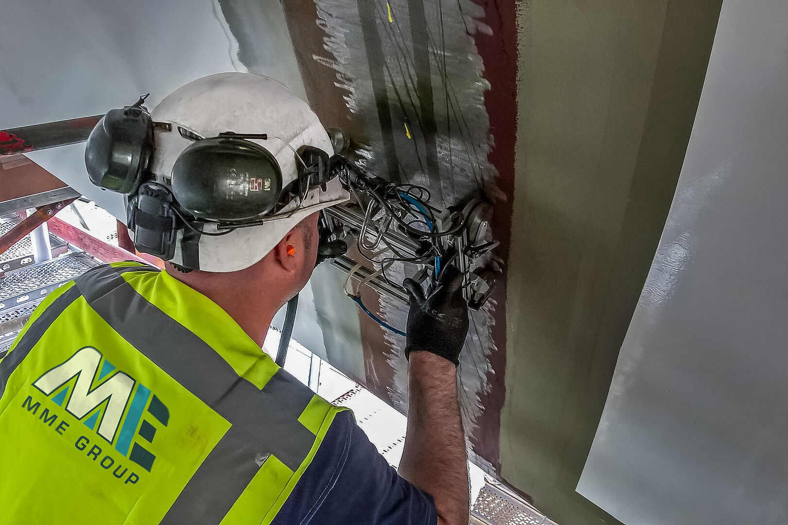
2. Placement of Transducers
Two ultrasonic transducers are used in the TOFD test - a transmitting transducer and a receiving transducer. The transmitting transducer emits Ultrasonic Waves into the material, while the receiving transducer detects the diffracted waves. Both transducers are placed on opposite sides of the weld or area of interest.
3. Calibration
Calibration is a crucial step in ensuring accurate results. Known reference notches or artificial reflectors are used to establish a baseline for the TOFD equipment. This allows for precise measurement and sizing of defects.
4. Scanning Process
The transducers are systematically moved along the surface of the material, maintaining a constant distance between them. As the Ultrasonic Transducers move, they emit ultrasonic waves and receive diffracted signals. The time taken for the diffracted signals to travel from the flaw to the receiving transducer is recorded.
5. Data Analysis
The recorded signals are processed and analyzed to create a visual representation of the internal structure of the material. This representation, often displayed as a TOFD image, provides detailed information about the location and size of any detected flaws.
Applications of TOFD
The TOFD test is widely applied in industries where the integrity of welded structures is of critical importance. Some of the key applications include:
1. Weld Inspection
TOFD is extensively used for evaluating weld inspection in various industries, including construction, Aerospace Industry, and manufacturing. It provides highly accurate information about the quality of welds, helping to identify and address potential issues.
2. Pressure Vessel Inspection
TOFD is employed to assess the Integrity of Pressure Vessels, ensuring they meet safety and regulatory standards. This is particularly crucial in industries such as oil and gas, petrochemicals, and power generation.
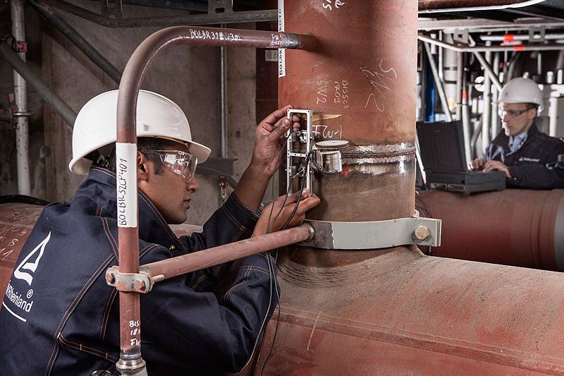
3. Pipeline Inspection
TOFD is used for inspecting pipelines, both onshore and offshore. It helps detect and characterize defects in Pipelines, reducing the risk of failure and ensuring the reliability of transportation systems.
4. Aerospace Industry
TOFD is applied in the aerospace sector to evaluate critical components like aircraft engines and structural elements. It aids in identifying potential defects that could compromise the safety and performance of aircraft.
When to use the Time of Flight Diffraction Test?

Time of Flight Diffraction Test is the best method to be used in the following circumstances:
- Any application where fault identification and precise height sizing are crucial
- With materials that aren't very granular; austenitic stainless steels, for instance, can't be subjected to TOFD.
- Pitting, corrosion, and erosion detection in pipe and plate material; however, this is limited to tiny regions due to the need for individual line scans.
- When Automated Ultrasonic Testing ( AUT) discovers isolated patches or significant corrosion/erosion, it is a useful confirmation tool. Large areas should still be screened using AUT.
- Identification of pores, small cracks, and crack confirmation.
- TOFD is the best monitoring tool for in-service problems since it offers more precise, repeatable examination in terms of height, length, and depth (it is more accurate in tenths of a millimeter as opposed to millimeters, which is a lower order of precision than Pulse Echo approaches).
Tools and Instruments Used in TOFD

Tools and Instruments Used in TOFD typically include ultrasonic transducers, wedges, calibration blocks, and a TOFD scanner. These tools are essential for ensuring precise and consistent results during the inspection process. Given below are the major instruments used in TOFD:
1. TOFD Tools
> Ultrasonic Transducers
These are the primary instruments used in TOFD. Ultrasonic Transducers are devices that convert electrical energy into high-frequency mechanical vibrations, and vice versa. They generate and receive ultrasonic waves, facilitating the detection of diffracted signals. The core component of an ultrasonic transducer is a piezoelectric crystal or ceramic element.
Piezoelectric materials have the unique property of generating an electric charge when subjected to mechanical stress and, conversely, deforming when subjected to an electric field. This bidirectional behavior enables them to convert between electrical and mechanical energy.
2. TOFD Equipment
Specialized TOFD equipment, including pulse generators, receivers, and data processing units, are used to control the ultrasonic waves, record signals, and generate visual representations of the material's internal structure.
> Calibration Blocks
These blocks, typically made of the same material as the test specimen, contain known reference notches or artificial reflectors. They are used to calibrate the TOFD equipment and establish baseline measurements.
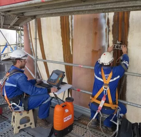
> Scanner Systems
Automated scanner systems are employed to ensure consistent and precise movement of the transducers along the surface of the material during the scanning process.
TOFD Weld Inspection Techniques

TOFD can be used along with other Ultrasonic Techniques or independently. Given below are some of the most widely used techniques:
- Single group TOFD
- Multiple TOFD
- TOFD with phased array
- TOFD with pulse-echo/creeping waves
1. Single Group TOFD
In Single Group TOFD, a single pair of Ultrasonic Transducers is used. One transducer emits an ultrasonic pulse while the other receives the diffracted signals. The depth and size of defects are determined based on the time-of-flight of the diffracted signals. Since it employs only one pair of transducers for inspection, it is a straightforward and relatively simple NDT Technique.
2. Multiple TOFD
Multiple TOFD involves using more than one set of Ultrasonic Transducers arranged at different angles. This allows for a wider coverage of the material being inspected, increasing the probability of detecting defects. It provides a broader inspection area compared to Single Group TOFD, enhancing overall inspection efficiency.
3. TOFD with Phased Array
Phased Array TOFD employs an array of ultrasonic elements that can be individually controlled to emit and receive Ultrasonic Waves at various angles. This allows for precise control of beam steering and focusing, enhancing defect detection and sizing capabilities. Phased Array TOFD provides advanced flexibility and versatility compared to conventional TOFD techniques. Since it allows for customizable beam steering, it enables inspectors to optimize the inspection for specific geometries and materials.
4. TOFD with Pulse Echo/Creeping Waves
This technique combines TOFD with other ultrasonic methods, such as pulse echo or creeping waves. Pulse echo involves sending an ultrasonic pulse and receiving reflections from the back wall or defects while creeping waves propagate along the surface of the material. By integrating these techniques, NDT Inspectors can gain additional information about the material's condition, complementing the data obtained through TOFD alone.
Differences between TOFD Techniques
Here are the key differences between the various Time-of-flight diffraction techniques discussed above:
1. Number of Transducers
Single Group TOFD uses one pair of Ultrasonic Transducers, while Multiple TOFD utilizes multiple sets of transducers arranged at different angles for a wider coverage area.
2. Integration with Other Techniques
TOFD with Pulse Echo/Creeping Waves combines TOFD with additional Ultrasonic Methods to gather more comprehensive information about the material's condition.
3. Phased Array Integration
TOFD with Phased Array incorporates a highly advanced array of ultrasonic elements with individual control, allowing for precise beam steering and focusing, providing enhanced defect detection and sizing capabilities.
4. Complexity and Versatility
Single Group TOFD is relatively simple, while Phased Array TOFD offers advanced flexibility and customization options, making it suitable for a wider range of inspection scenarios.
Each of these TOFD techniques offers unique advantages and can be applied based on specific inspection requirements, material properties, and the desired level of detail in defect detection and characterization
What are the Examples of TOFD?
Underwater welds of a repaired building were inspected at a speed of 45 minutes per platform in the North Sea. Employing the conventional Radiography Technique would have taken 16 to 29 hours. The test was conducted at a very high speed on eight gas containers with 2000 m welds in West Java. 60–100 m of welds were checked daily using TOFD.
The Netherlands Welding Institute (NIL) reported that compared to other NDT Techniques, the TOFD methodology had a higher chance of detection and reduced test costs. TOFD is 1.3 times more reliable than radiography and twice as reliable as manual UT.
What are the Drawbacks of the TOFD Technique?
The TOFD only measures the duration of flight, not the amplitude of the diffracted echoes, as per the European standard. No diffracted echo would be seen in the TOFD image if the instrument sensitivity was set extremely low. The TOFD image will show a lot of diffracted echoes if the instrument sensitivity is adjusted slightly over the electronic noise level. These echoes are created by extremely minor weld seam inhomogeneities and do not necessarily indicate a poor-quality weld. Since the conducted test usually requires acceptance criteria, it is also important to define a gain or an amplitude level for the TOFD approach.
The fact that TOFD requires extremely high gain, which results in extremely high back wall echo makes it unsuitable for materials with coarse grains, such as Inconel and austenitic stainless steel. The crack tip echoes are a component of a noise region resulting from other insignificant diffracted echoes of inhomogeneity. That can make sizing with the TOFD technique impossible.
A TOFD image NDT Inspector needs to perform depiction decisions similar to those used in radiography. He or she must distinguish the relevant echoes. Finding old flaws inside the weld seam is typically not that relevant for an in-service examination of welds. On the other hand, finding cracks in the back of pipes or containers is very crucial.
For example, defects of 0.5 mm in depth and around 10 mm in length in a pressure component or container with a wall thickness of 30 mm must be examined. It is not feasible to use diffracted echoes for this since the fracture tip echo amplitude is relatively tiny this close to the back wall. In this scenario, one must employ the mirror effect and conventional Ultrasonic Testing Methods using angle beam probes.
Probe frequencies under 5 MHz are not appropriate; they must be 10 MHz or greater for employing TOFD. The edges of cracks need to be sharp while inspecting with TOFD, although they aren't always. It's not always possible to assume that a crack's angle is vertical. The magnitude of return signals of TOFD may be significantly impacted by the angle of the crack.
Below the surface, there is a dead zone for fault identification. This indicates that flaws near the surface are not visible always. The Magnetic Particle Test or the creeping wave probe test can be used to make up for this. A minimum of 6mm of thickness and a 4-inch diameter are needed. There is no upper limit to the thickness; it could reach several hundred micrometers. When it comes to measuring and identifying defects that are parallel to the inspection surface, TOFD is ineffective. 'Included' faults like porosity and slag caused by manufacture cannot be fixed by TOFD.
Things to Think About When Using TOFD
Access to both sides from a single surface is necessary for the technique. Access may occasionally be limited since a probe must run on both sides of the weld. For ToFD to be used efficiently, specialized technology and in-depth operator experience are needed. TOFD should be used with another Ultrasonic Method, such as phased array ultrasound or traditional pulse-echo ultrasound. The ToFD dead zone at the top and bottom surfaces of the inspected object is covered by this complementary approach. Additionally, it enables a fast reference to any indications' axial placement. It is challenging to use on pipes with a diameter of less than 4 inches or parts with a thickness of little more than 6 mm.
Manual TOFD vs Automatic TOFD
Automatic TOFD inspection is a very beneficial option when higher POD, increased accuracy, more measurements, quicker procedures, and no human intervention are required. By taking several readings and averaging the results, automatic TOFD is able to provide a solution that reduces or even eliminates mistakes. When measurements need intricate setup, triggering, result questioning, and assessment processes, automated TOFD is preferred since it is a quicker process.
In these situations, manual measurement methods are inherently slow. In contrast, an automated TOFD system can complete these tasks far more quickly. Since measurements are only obtained once during a manual test, there may be numerous inaccuracies introduced. When there are uneven surfaces, it is very difficult to maintain constant force contact and speed while using a manual system. Rugs with non-smooth surfaces are frequently unable to accurately scan a material with a manual method due to fluctuating speed and non-constant force contact. On the other hand, because of their continual force contact and speed, automated systems can scan the same surfaces more effectively.
Advantages of Time of Flight Diffraction
- It is an extremely accurate method for sizing vertical faults that operates in a single pass and is not amplitude-dependent.
- The NDT Method is proven to be significantly more accurate than traditional pulse-echo approaches, which rely on echo amplitude, in estimating the height of faults.
- The intrinsic precision in fault sizing, particularly in-depth, is the main reason behind the popularity of the ToFD method, along with its high chance of detection, low false call rate, and portability. Similar to Radiographic Testing Film, TOFD gives a quick visual representation of the weld by scanning the cross-section, enabling a prompt preliminary study of the material/weld state.
- Compared to the Phased Array, this visual representation is simpler to offer to a client because it presents the data as a single, fully visible strip chart.
- When sizing imperfections, especially crack-like planar defects, ultrasonic diffraction offers clear advantages.
- Diffracted waves start at the fracture points during a ToFD inspection.
- The information on the spatial relationship between the crack points and, consequently, the extent of the crack, is carried by the difference in the time of flight of these waves.
- Due to the scattering or absorption of the ultrasonic signal, Phased Array Ultrasonic Testing/Pulse Echo Ultrasonics may miss volumetric indicators, however, ToFD detects all indications regardless of orientation.
- ToFD scanning is fast and requires little space for the data files.
Key Takeaways
- Ultrasonic Time of Flight Diffraction is an advanced, computerized NDT Method known for its high accuracy and detailed defect assessment capabilities.
- TOFD relies on Ultrasonic Wave Propagation and diffraction to evaluate weld integrity and detect flaws or defects.
- It involves generating high-frequency ultrasonic waves through a transducer, which interacts with the material's internal structure. Flaws cause diffraction of the waves, providing information about size, shape, and location.
- The Time of Flight Diffraction procedure includes surface preparation, placement of Ultrasonic Transducers, calibration, systematic scanning, and data analysis.
- It is widely applied in industries like construction, aerospace, manufacturing, Oil and Gas Industry, and power generation for weld inspection, pressure vessel assessment, pipeline inspection, and aerospace component evaluation.
- This is best used for applications where fault identification and precise height sizing are crucial, but may not be suitable for materials like austenitic stainless steels.
- It offers advantages including high probability of detection, low false call rate, and accurate sizing of defects, making it a valuable Non-destructive Evaluation Method.
- Considerations for Time of Flight Diffraction implementation include access to both sides of the material, operator experience, and the need for complementary techniques in certain scenarios.
- Factors like material properties, surface conditions, and defect type influence the choice of this technique (Single Group TOFD, Multiple TOFD, TOFD with Phased Array, etc.).
- TOFD offers advantages like a high probability of detection, a low false call rate, and accurate sizing of defects, making it a valuable NDE Method.
- Considerations for Time of Flight Diffraction implementation include access to both sides of the material, operator experience, and the need for complementary techniques in certain scenarios.
FAQs
1. Can TOFD perform all NDT tasks?
A: TOFD is particularly helpful in fault identification and sizing, especially for vertical faults, but may only be suitable for some NDT tasks due to limitations in certain conditions and material types.
2. What is the difference between UT and TOFD?
A: TOFD, unlike conventional Ultrasonic Testing, provides enhanced accuracy in fault sizing, independence from amplitude variations, and detection of indications regardless of orientation.
3. What are the defects of TOFD?
A: The limitations of TOFD include challenges with certain materials such as materials with coarse grains, a dead zone for fault identification near the surface, and difficulties in sizing defects under specific conditions.
References:
1. Wikipedia
2. Phoenix ISL
3. Olympus IMS
4. IPEC
5. NDT.NET


