Table of Contents
- Introduction
- How ECT Detects a Defect
- Surface-Breaking Cracks
- Subsurface and Near-Surface Flaws
- Corrosion, Pitting and Wall Loss
- Weld Defects
- Material Conditions ECT Detects That Are Not Defects
- What Eddy Current Testing Cannot Detect
- What Affects Whether a Defect Is Detected?
- Summary Tables
- Conclusion
- FAQs
Introduction
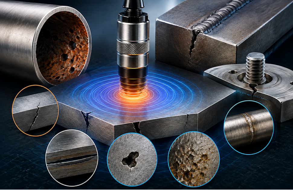
Eddy Current Testing (ECT) is used for the detection of surface-breaking cracks, near surface defects, pitting, corrosion, wall loss, some selected weld defects and variations in material properties in electrically conductive materials. The frequency and probe design and material properties determine the depth and direction of cracks that can be detected, and as such is most effective for detecting surface cracks.
How ECT Detects a Defect
A defect is detected when ECT interferes with the flow of eddy currents that are created in an electrically conductive material. The probe forms a varying electromagnetic field which induces surface currents in the component. The electromagnetic response is altered by the presence of a crack, pit, void, inclusion or thickness change, and an indication is recorded. The ability and the limitations of ECT can be explained in terms of this simple principle: A flaw needs to interact with the eddy current field to a degree that it can be detected. Thus the detection is directly influenced by the depth, orientation, material properties and frequency of the probing as well as by the probe design and lift-off.
Please refer to our in-depth Eddy Current Testing (ECT) Guide for further details.
Please refer to our in-depth guide for the full principles behind eddy current inspection.
→ Read: Eddy Current Testing: A Complete Guide
Surface-Breaking Cracks
Eddy Current Testing is one of the most common applications is surface breaking cracks. Eddy currents are concentrated near the surface of the material being inspected, so that ECT can provide high sensitivity to small cracks that reach or extend just below the surface.
Common examples include fatigue cracks, stress-corrosion cracking (SCC), grinding cracks and heat-treatment cracks. They can be around holes in the fastener, edges, or weld areas, in areas of stress, and in areas prone to thermal change, among other areas.
The minimum size detectable depends on the specific type of ECT inspection and the conditions applied, but under ideal conditions, cracks as small as 1 mm or less can be detected. The real limit will vary with the probe, frequency, material, surface condition and calibration and signal to noise.
It is important to crack orientation. Frequently the best indications will occur in cracks that are at right angles to the predominant direction of the eddy current flow. Cracks parallel to the existing cracks can produce a significantly lower response and go undetected. The multi-directional scanning increases the chance of detection when the orientation of the crack is not known.
Subsurface and Near-Surface Flaws
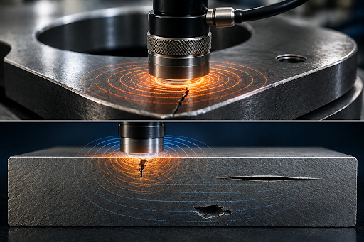
Some defects can be identified with ECT, however, this is limited. Don't be fooled by the word subsurface; this is not deep volumetric inspection.
Some of the areas that could be affected include voids, inclusions, laminations and shallow cracks, as well as cracks around bolt holes and under some fastener heads. Whether the flaw is in the effective eddy current field or not determines the detection.
The standard depth of penetration is the depth where the eddy current density is reduced by 37% from the surface value. For practical applications, the conventional ECT usually only has a certain depth of penetration, in the order of a few millimetres, and depends on the material and frequency.
Lower frequencies can have greater penetration, but typically with decreased surface sensitivity and resolution. Ultrasonic testing (UT) is usually more appropriate for deep internal discontinuities and/or true volumetric inspection.
Corrosion, Pitting and Wall Loss
This is a widely used technique for the detection of pitting corrosion, localized corrosion, wall thinning, erosion and damage of tube supports (also known as tube supports loss of section). This will vary according to the material of the component and its geometry for inspection.
Traditional ECT can be used to detect pitting, cracking and localized degradation of non-ferromagnetic tubes.
Conventional ECT is more difficult for ferromagnetic tubes. Therefore, Remote Field Testing (RFT) is typically employed to check for corrosion, erosion and other defects in the wall of a tube.
Near Field Testing (NFT) is primarily used to detect the degradation of the ID in ferromagnetic tubes, especially in fin fan heat exchangers or air coolers.
Pulsed Eddy Current (PEC) can be used to inspect the underlying conductive material without completely removing the covering layer for corrosion underneath. PEC is applicable for screening under-insulated and other coated structures.
The techniques are not interchangeable as they are all tailored to specific materials, geometries and inspection goals.
Conventional ECT struggles on ferromagnetic tubes, which is why Remote Field Testing is the standard alternative for wall-loss detection in these materials.
→ Read: What Is Remote Field Testing
Weld Defects
Selected weld defects, especially surface and near surface defects can be detected by ECT. An important example is weld toe cracks which can significantly affect the path of eddy currents if they break the surface.
ECT can also identify some lack of fusion in the near-surface region and surface and near surface porosity, depending on the configuration.
Ferromagnetic welds are more difficult because variations in magnetic permeability between weld, HAZ and base material can result in strong background signals. Specialist techniques like Alternating Current Field Measurement (ACFM) or ECT with magnetic saturation, may therefore be used.
But, volumetric weld inspection is not a substitute for ECT. It may not be effective if the discontinuities are deep lack of fusion, internal porosity, and other discontinuities buried within. For deeper welds, a UT, PAUT or RT might be more suitable.
Material Conditions ECT Detects That Are Not Defects
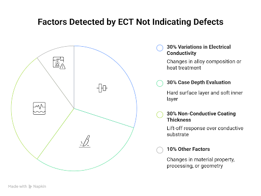
ECT is able to detect changes in material characteristics without the presence of any material defect.
Variations in electrical conductivity can suggest compositional changes in alloys, variations in the condition of the alloy through heat treatment or other factors. This means that ECT can be utilized for alloy verification or heat-treatment verification.
Case depth can also be evaluated through specialized applications which include a hard, surface layer and a soft layer below.
ECT can also measure non-conductive (lift-off) coating thickness over a conductive substrate by measuring the lift-off response between the probe and the substrate.
So an ECT indication doesn't necessarily mean a fault. It could also be a change in a material property, processing condition and geometry.
What Eddy Current Testing Cannot Detect
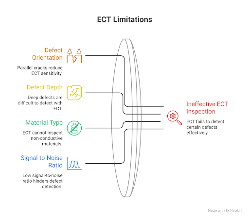
However, there are significant drawbacks to ECT which should be taken into account before choosing it as the inspection method.
Sensitivity may be reduced by unfavourable defect orientation. ECT is sensitive to the disturbance of the flow of current, so a crack parallel to the flow of the current can give a weaker indication than a crack that cuts across the current.
Another restriction is deep volumetric defects. The eddy current density falls rapidly with depth and a defect which is deep within a thick component can have a relatively small effect at the surface. The effect of lower frequencies is that penetration may be increased, but ECT is still a near-surface technique. Generally, UT is more suitable for deep material inspection.
Also, since eddy currents cannot be generated in non-conductive material (such as plastics, ceramics, glass, and many non-reinforced composites), this cannot be performed directly with ECT. Penetrant Testing (PT) can be used for appropriate surface breaking defects in such materials.
Radiographic Testing (RT) or UT might be more appropriate for deep internal weld discontinuities.
Lastly, a flaw could exist, but not be detected in practice. If the signal is too small compared to the background noise, material variation or geometric signals, then reliable identification may be impossible.
For non-conductive materials where ECT can't be used at all, Penetrant Testing remains the standard alternative for surface-breaking defects.
→ Read: Liquid Penetrant Testing Guide
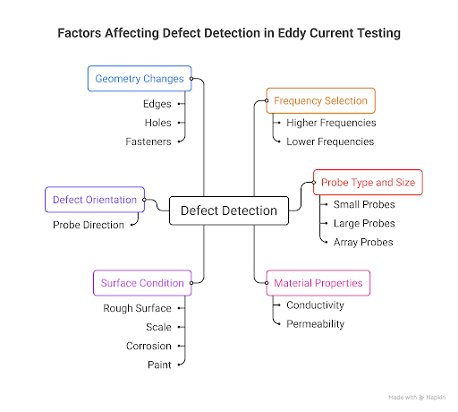
What Affects Whether a Defect Is Detected?
There are multiple inspection variables that affect whether or not a defect will result in a detectable signal.
The level of penetration and surface sensitivity can be controlled using frequency selection. Higher frequencies are better for shallow defects and lower frequencies yield greater penetration.
The sensitivity and coverage are affected by the type and size of the probe. There are small probes that can give a detailed inspection of a smaller area or larger or array probes that can give an inspection of a wider surface.
Material conductivity and permeability affect the eddy current response. In the case of ferromagnetic materials it is more significant to review the permeability as it can produce strong background signals.
Surface condition also is important. Probe lift-off due to rough surface, scale, corrosion, paint, etc. may reduce sensitivity.
The strength of the defect that interferes with the flow of current is determined by defect orientation. The direction of the probe can thus be altered to increase the sensitivity to detect cracks in varying orientations.
Lastly, geometry changes such as edges and holes or fasteners can produce signals that mimic defects. The geometric response must be distinguished from genuine indications by using proper calibration and interpretation.
Summary Tables
Conclusion
Eddy Current Testing is best suited for surface and near-surface defects in electrically conductive material. It is used for the major applications of fatigue cracks, SCC, grinding cracks, pitting, corrosion, tube degradation and selected weld defects. Specialized techniques expand ECT to ferromagnetic tubing, corrosion underneath insulation (and other applications).
But ECT is not the standard method of inspection. Detection will be affected by the depth of the defect, the orientation and size of the defect, material properties, frequency, probe design, lift-off and component geometry.
The best practice is therefore to match with the material – type of defect – inspection objective. If the flaw is not in the range of ECT's feasibility, other techniques like UT, RT or PT should be used.
FAQs
How small a crack can Eddy Current Testing detect?
A special type of ECT inspection can be used for detecting cracks at depths significantly below 1 mm, under favourable circumstances. There is no minimum detectable size, however, that is universal. The size of the smallest flaw that can be reliably detected is affected by the probe design, the frequency of the probe, the type of material being investigated, the direction of the crack, the surface condition, the signal-to-noise ratio, and calibration.
How deep can Eddy Current Testing detect?
ECT is a "near surface" and surface method. It is highly sensitive to depth with shallower penetration with higher frequencies. For many applications useful subsurface detection is restricted to a few millimetres. Deeper flaws usually need ultrasonic or other appropriate volumetric inspection methods.
Can Eddy Current Testing detect internal defects?
Some of the discontinuities located close to the surface can be detected by the use of ECT if they lie within the depth penetration range of ECT. Normally not recommended for deep volumetric defects. UT is the most common choice for the inspection of information that will be needed for deeper sections of a component or internal discontinuities.
Does Eddy Current Testing work on welds?
Yes. Some surface and near surface weld defects, particularly cracks, can be detected with ECT. Welds that are ferromagnetic can be difficult to work on because of the background signals created by the variations in permeability. For certain applications ACFM or saturation-based techniques can be employed, and for volumetric weld inspection, UT or RT is more appropriate.
Will Eddy Current Testing be able to detect defects under paint?
Yes, ECT can inspect under certain non-conductive coatings. But as the thickness of the coating increases, greater lift-off occurs and sensitivity will decrease. Pulsed Eddy Current may be helpful in assessing corrosion and/or wall loss even through thick coatings or thick insulation materials where removal of the coating is not desired.
Does defect orientation affect ECT detection?
Yes. The sensitivity of ECT can be greatly influenced by the orientation. The stronger the indication, the longer the crack is oriented perpendicular to the dominant eddy current flow; a weaker indication may be obtained when the crack is oriented parallel to the dominant eddy current flow. An orientation change in the direction of the scanning or the orientation of the probe can increase the chances of finding cracks oriented in a different direction.


There are no comments yet!