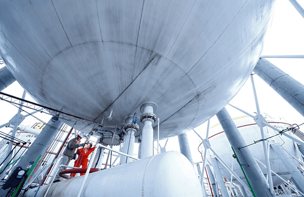
Most non-destructive testing methods examine a structure that is standing still. Radiography, ultrasonic testing, magnetic particle inspection and eddy current testing all interrogate an asset that is unloaded, drained or shut down, and they answer a specific question: What discontinuities exist in this component right now?
That question leaves a gap. A crack that is stable under no load may extend under working pressure. A corroded tank floor reveals nothing to a surface inspection until the product is drained. Damage that only expresses itself under stress is invisible to a method that inspects the structure at rest.

Acoustic emission testing closes that gap. It is a passive method: rather than transmitting energy into the material and interpreting what comes back, it listens for the energy the material releases on its own while it is being loaded. That single difference, passive rather than active and dynamic rather than static, is why acoustic emission occupies a position no other NDT method fills.
What acoustic emission actually measures
ASTM E1316, which sets the terminology used across non-destructive examination, frames acoustic emission around two things happening together: energy escaping suddenly from a small region inside a material, and the short-lived elastic waves that this escape produces.
In practice, that means something inside the material moves suddenly. A fatigue crack advances a fraction of a millimetre. A fibre snaps in a composite laminate. A corrosion product fractures and detaches. Each of these events releases stored elastic energy as a stress wave that travels outward through the material to the surface, where piezoelectric sensors detect the microscopic surface displacement and convert it into an electrical signal.
These waves sit above the audible range. Acoustic emission testing generally works between 20 kHz and 1 MHz, and in metals the useful band is typically narrower, commonly 100 kHz to 400 kHz, with signal processing chains built to isolate that region and reject lower-frequency plant noise from pumps, engines, wind and flowing fluid.
The critical consequence follows directly from the physics: acoustic emission only detects defects that are active. A crack that is not growing releases no energy and produces no signal. A stable void sits acoustically silent no matter how large it is. This is simultaneously the method's greatest strength and its most important limitation, and any competent test plan is built around it.
Most non-destructive testing methods examine a structure that is standing still. Radiography, ultrasonic testing, magnetic particle inspection and eddy current testing all interrogate an asset that is unloaded, drained or shut down, and they answer a specific question: what discontinuities exist in this component right now?
That question leaves a gap. A crack that is stable under no load may extend under working pressure. A corroded tank floor reveals nothing to a surface inspection until the product is drained. Damage that only expresses itself under stress is invisible to a method that inspects the structure at rest.
Acoustic emission testing closes that gap. It is a passive method: rather than transmitting energy into the material and interpreting what comes back, it listens for the energy the material releases on its own while it is being loaded. That single difference, passive rather than active and dynamic rather than static, is why acoustic emission occupies a position no other NDT method fills.
What acoustic emission actually measures
ASTM E1316, which sets the terminology used across non-destructive examination, frames acoustic emission around two things happening together: energy escaping suddenly from a small region inside a material, and the short-lived elastic waves that this escape produces.
In practice, that means something inside the material moves suddenly. A fatigue crack advances a fraction of a millimetre. A fibre snaps in a composite laminate. A corrosion product fractures and detaches. Each of these events releases stored elastic energy as a stress wave that travels outward through the material to the surface, where piezoelectric sensors detect the microscopic surface displacement and convert it into an electrical signal.
These waves sit above the audible range. Acoustic emission testing generally works between 20 kHz and 1 MHz, and in metals the useful band is typically narrower, commonly 100 kHz to 400 kHz, with signal processing chains built to isolate that region and reject lower-frequency plant noise from pumps, engines, wind and flowing fluid.
The critical consequence follows directly from the physics: acoustic emission only detects defects that are active. A crack that is not growing releases no energy and produces no signal. A stable void sits acoustically silent no matter how large it is. This is simultaneously the method's greatest strength and its most important limitation, and any competent test plan is built around it.
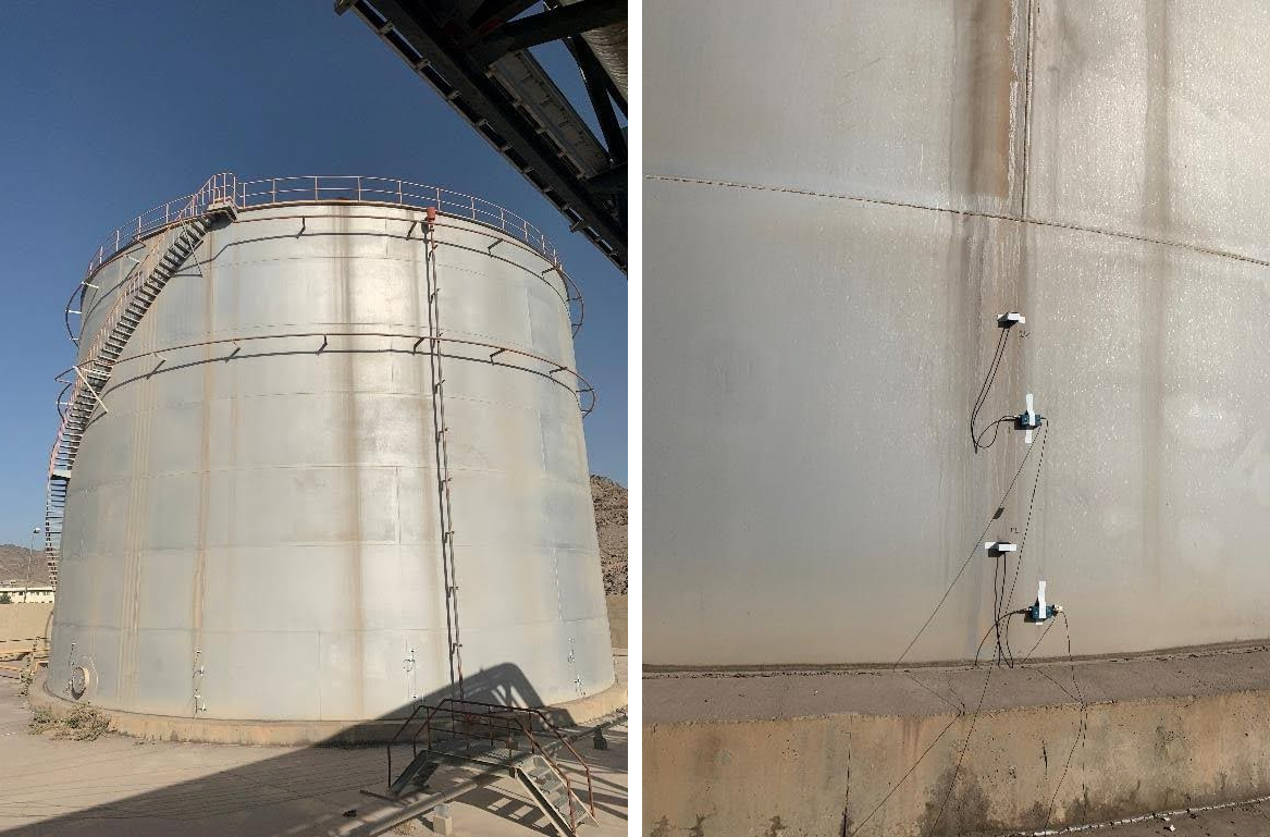
AE condition Monitoring of Bottom Plate in Progress
Why load is not optional
Because the material has to generate the signal itself, an acoustic emission test requires the structure to be stressed. This is the subject of its own ASTM standard practice, E569/E569M-20, which covers monitoring during controlled stimulation. It addresses assets that can be put under stress mechanically or thermally, vessels and piping among them, and it treats the job of the monitoring system as threefold: finding emission sources, working out where they are, and sorting them by type using wave parameters.
That practice is also specific about what produces the signals. Applying load to a flawed region can set off emission in more than one way. The flaw may simply extend. A brittle oxide layer over the damage may crack. Crack faces that have bonded together can tear apart as load comes on, or grind against each other as the geometry shifts.
The stimulus takes different forms depending on the asset. A pressure vessel is pressurised hydrostatically or pneumatically. A bridge span is loaded with test vehicles or ballast. A storage tank uses its own product head, with the tank filled to a working level for condition monitoring. A composite structure is loaded mechanically in a test frame. In each case the load is the interrogating agent, the equivalent of the ultrasonic pulse in a conventional inspection, except that the structure supplies the response.
The Kaiser effect and the Felicity ratio
Loading a structure once tells you something. Loading it, unloading it, and loading it again tells you considerably more, and this is where acoustic emission becomes genuinely diagnostic rather than merely detective.
The Kaiser effect is a silence. Take a sound structure, load it to some level, take the load off, then load it again. Nothing registers on the sensors until you push past wherever you stopped last time. The material behaves as though it remembers the worst stress it has already come through, and has nothing new to report until you exceed it. Kaiser effect is very useful in determining structural deficiencies which are load sensitive such as cracks and mechanical deformation.
Damage erodes that silence. In a structure carrying accumulated damage, the sensors pick up activity below the earlier peak, which is the Felicity effect. How far below is captured by the Felicity ratio: take the load at which meaningful activity restarts, divide it by the earlier peak load, and the resulting number is the measure. Felicity effect/ratio is widely used to test the composite structures for defects.
The interpretation is straightforward. Where the Kaiser effect holds fully, the ratio equals 1.0. As damage accumulates the ratio falls below 1.0, because the structure begins emitting at progressively lower loads. Work published through RILEM Technical Committee 212-ACD notes that in a very sound structure the ratio can even exceed 1.0, while repeated damage in reinforced concrete beams drives it downward, making the ratio a usable indicator of damage accumulation and structural instability.
Published laboratory work gives a sense of the scale involved. In cyclic shear tests on rock joints, the Felicity ratio decreased steadily as damage progressed, reaching approximately 0.94 to 0.99 at final shear failure. In composite pressure vessels, the ratio has been observed falling across successive pressurisation sequences as an inserted failure mechanism grew.
One important caveat: the Kaiser effect is not universally reliable. Time-dependent damage mechanisms such as corrosion and hydrogen embrittlement can undermine it, and in concrete it does not hold completely at high stress levels. The ratio is a strong indicator, not an unconditional rule.
What the load hold reveals
If there is a single most diagnostic moment in an acoustic emission test, it is the hold.
A well-designed loading sequence does not ramp continuously to maximum. It steps up and pauses. A pressurisation sequence following ASME Boiler and Pressure Vessel Code Section V, Article 12 typically advances in increments (commonly 50%, 65%, 85% and 100% of maximum test pressure, with an option to reach 110%), pausing at each step. Hold periods are typically ten minutes at each increment, with a substantially longer hold at the final level.

The logic is simple. During a hold, the load is constant, so a structurally sound region should fall silent. Emission that continues while the load is unchanging indicates something is still moving inside the material: the signature of an actively growing discontinuity rather than a settled one.
This is also where experience matters. Take a vessel that has never been stress-relieved by post-weld heat treatment. The first time it is pressurised, material around weld details and geometric transitions yields locally, and yielding is noisy. Those signals are real emission, but they reflect a vessel bedding in rather than a flaw. Assessors handle this by narrowing what they count on that first run: the loudest hits, and whatever arrives once the pressure has stopped climbing. Some materials behave differently again: fibre-reinforced polymers can continue emitting at constant load because of the viscoelastic response of the resin and fibres, while structures with hydrogen-induced cracking may never stabilise under hold at all.
Where this is applied
Storage tanks. Tank floors are the classic case for load-based acoustic emission monitoring, because a conventional internal inspection requires the tank to be drained, cleaned and entered, which is expensive and takes the asset out of service. Acoustic emission allows the floor to be assessed while the tank remains in operation, detecting active corrosion, material discontinuities and leaks, and producing a graded condition assessment that helps operators prioritise which tanks genuinely need to be opened under their API 653 programme.
Pressure vessels. ASME Section V provides three dedicated articles: Article 11 for fibre-reinforced plastic vessels, Article 12 for metallic vessels during pressure testing, and Article 13 for continuous monitoring. ASME Section VIII Division 2 can call for acoustic emission testing during a hydrostatic or pneumatic test in accordance with Article 12, where the User's Design Specification requires it. Monitoring during pneumatic testing is particularly valued, because it provides early warning of defect growth during an inherently higher-risk test.
Bridges and civil structures. Load testing of bridges is a natural fit. In a widely cited 2020 study, researchers instrumented a decommissioned 1968 prestressed concrete bridge span and subjected it to progressively increasing load and unload cycles to failure, showing that acoustic emission features (hit counts, amplitude, signal strength and peak frequency) could detect and classify damage as it developed.
Composites and wind turbine blades. Blade certification testing has used acoustic emission during static and fatigue loading, though the field has been candid about the difficulty: damage criticality can be judged from emission during long load holds in an ultimate strength test, but such holds do not represent loads the blade would actually see in service.
Marine & Aerospace: Evaluating fatigue crack propagation and corrosion activity on ship hulls, offshore platforms, and aircraft components during active operation
The honest limitations
Acoustic emission under load is powerful, but it is not a complete answer and presenting it as one damages credibility.
It is largely qualitative. It tells you that a structure has a problem, roughly where, and gives a measure of severity. It does not size a flaw or determine its type. A complementary method, usually ultrasonic testing, is needed to characterise and size what acoustic emission has found.
It is blind to dormant defects. If the applied load is insufficient to make a flaw active, that flaw goes undetected.
It is noise-sensitive. Industrial environments are acoustically hostile, and separating genuine emission from mechanical and electrical noise requires proper filtering, sensible threshold selection and experienced interpretation.
It is attenuation-limited. Signals weaken with distance, which constrains sensor spacing and, on very large assets such as modern high-capacity tanks, can leave parts of the structure outside reliable coverage.
And it is operator-dependent. Interpretation is a skilled task; the same dataset can support different conclusions in different hands, which is why personnel qualification under ASNT SNT-TC-1A or ISO 9712 matters as much as the instrumentation.
Key takeaways
Acoustic emission testing answers a question no static inspection method can: is this structure sustaining damage right now, under the loads it actually carries? It does so by listening rather than probing, which makes load an essential part of the test rather than an inconvenience.
The Kaiser effect, the Felicity ratio and the behaviour of emission during a load hold together form the interpretive framework that turns raw signals into an integrity judgement. Used within its limits, as a global screening and prioritisation tool that directs more precise methods to the right locations, it is one of the few techniques capable of catching damage while it is still developing.
Sources
- ASTM E1316, Standard Terminology for Nondestructive Examinations: definition of acoustic emission.
- ASTM E569/E569M-20, Standard Practice for Acoustic Emission Monitoring of Structures During Controlled Stimulation: scope and emission source mechanisms (ASTM International).
- ASME Boiler and Pressure Vessel Code, Section V, Articles 11, 12 and 13: acoustic emission examination of FRP vessels, metallic vessels during pressure testing, and continuous monitoring.
- ASNT Pulse, NDT Method Overview: Learn the Basics of AE Analysis for Field Testing: Kaiser effect definition.
- RILEM Technical Committee 212-ACD recommendation, Materials and Structures: Felicity ratio interpretation and behaviour in concrete.
- Hou et al., Investigation on Acoustic Emission Kaiser Effect and Frequency Spectrum Characteristics of Rock Joints Subjected to Multilevel Cyclic Shear Loads, Geofluids (2021): Felicity ratio values at failure.
- Tonelli, Luchetta, Rossi, Migliorino & Zonta, Structural Health Monitoring Based on Acoustic Emissions: Validation on a Prestressed Concrete Bridge Tested to Failure, Sensors 20(24), 7272 (2020).
- A Review on Acoustic Emission Testing for Structural Health Monitoring of Polymer-Based Composites, PMC (2023): emission behaviour under constant load in FRP.
- Acoustic Emission Monitoring from Wind Turbine Blades Undergoing Static and Fatigue Testing, NDT.net: load-hold criticality assessment.
- Using the acoustic emission method for testing aboveground vertical storage tank bottoms, Applied Acoustics (Elsevier): in-service tank floor assessment.
- ScienceDirect Topics, Acoustic Emission Testing: global monitoring, qualitative nature, need for complementary methods.