
Modern civilization is filled with all manner of sounds ranging from the subtle chirp of the birds to the sounds produced in inaudible frequencies by distant Supermassive Blackholes at the center of galaxies far away. Audible sounds represent only a facet of information that can be accumulated by observing ambient noise, owing to the sophisticated devices and sensors available specific to the user's purpose.
Acoustics refers to the study of sound as a science, which can be dated back to the 6th century BC when Pythagoras analyzed notes of musical instruments to understand complex mathematical equations. This study of sound led Lazzaro Spallanzani to the discovery of Ultrasound in 1793 as he observed Echolocation as a phenomenon used by various beings like Barn owls and bats. These observations indicated that detecting prey and obstacles during flight, even in conditions with dim light or darkness, was attributed to their sense of hearing rather than the ability to perceive sight.

Echolocation observed in bats using Ultrasonic waves to detect obstacles (Image credits: Journal of Comparative Physiology A 202 (2016))
The frequencies of sound above 20 Kilohertz are referred to as ultrasonic frequencies. Ultrasound and, thereby, ultrasonic frequencies lie above the range of sounds audible to a Healthy Human adult. Hence a requirement for devices and instruments to perceive and generate them has led to great technological advancements. This instrumentation has been employed for many purposes in the fields of Medicine, Infrastructure testing, and Target detection (SONAR).

Sound frequency ranges (Image credits: J Bioeng Biomed Sci 6.184 (2016))

SONAR used for both Target detection (Left) and Earth Bed analysis (Right) (Image credits: UNIT 4 Ultrasonics – KanchiUniv)
Non-destructive Testing and engineering (NDT/NDE) allow the inspection of structures and infrastructure through Non-Invasive and Non-destructive methodologies for deformities and structural defects. Ultrasound used as a medium to carry out Non-destructive testing began in the early 1950s and has continued presently as Ultrasonic Testing (UT). The nature of the testing brings to analysis an important parameter as the Defect size of the ultrasonic testing, which constrains the frequency of the ultrasound and the equipment used for the testing. As discussed in the successive sections, an intricate comprehension of Ultrasonic testing is imperative to understand this parameter.
WHAT IS ULTRASONIC TESTING
Ultrasonic testing is a non-destructive technique using ultrasound as an inspecting medium through Structural strata. A crystalline piezoelectric material such as Quartz, which produces vibrations when electricity is conducted through them, is used in a Transducer to generate high-frequency ultrasonic waves onto the structure under analysis.
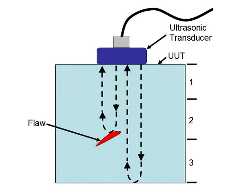
Ultrasonic testing a structure (Unit under test/UUT) (Image credits: UNIT 4 Ultrasonics – KanchiUniv)
The ultrasonic waves thus generated are transmitted through the structure and reflected from the back surface after transmitting back and forth through the strata without flaws.

As observed in the oscilloscope, the ultrasonic waves reflected by the back surface (Image credits: NDTA, Wellington, New Zealand)
The presence of a discontinuity in the layers would cause a portion of the waves to be reflected, a portion absorbed, and the waves around the discontinuity transmitted without interruptions since the wave reflected from the discontinuity reaches the transducer before the wave reflected from the back surface a delay is detected at the transducer along with a difference in amplitude. The mechanical ultrasonic waves detected at the transducer are converted to electricity by the piezoelectric material in the core, which is further transmitted to a processing device like an oscilloscope to generate data from the electricity to be perceived by the tester. The time the reflected wave takes from the back surface helps the tester calibrate the structure's thickness.

The oscilloscope detects cracks due to the partial reflection of waves at the cracks (Image credits: NDTA, Wellington, New Zealand)
The electric signal received at the Measurement device/oscilloscope relays the difference in time of the ultrasonic pulses and the difference in wave energy giving accurate information about the location and thickness of the discontinuity hence observed. This data helps the tester inspect the flaws present at the surface and the strata without invading the integrity of the material.
ULTRASONIC EQUIPMENT AND ITS SCHEMATICS
Ultrasonic testing involves devices responsible for converting electrical energy from the power source to mechanical ultrasonic waves (Transducers) facilitated through a medium (Couplant) which helps propagate the waves through all layers of the structure. This setup requires the precise ultrasonic generation and reception capabilities (Pulser-Receiver) for the waves reflected in the testing process and a processing unit capable of comprehensively displaying the energy signals related to the ultrasonic Waves (Oscilloscope/ Electronic test Display).
Also Read, Acceptance Criteria for Liquid Penetrant Testing

Ultrasonic testing setup (Image credits: Composite structures 93.5 (2011))

Schematics of a contemporary ultrasonic testing setup and the equipment involves (Image credits: IOWA State University NDE-Ed)
The equipment used in ultrasonic testing, as indicated in the schematics above, varies depending on the angle of wave propagation and the ambient medium used to carry out the test. The details of the equipment and variations about specific applications are discussed in the successive sections.
Transducers:
These devices are responsible for converting electrical to mechanical energy and vice-versa. Contemporary transducers employ piezoelectric elements as core materials since these elements generate electricity corresponding to mechanical stimuli and mechanical waves from electrical signals to generate Ultrasonic waves.

Cross-sectional (Left) and explosive view of an Ultrasonic Transducer (Image credits: IOWA State University NDE-Ed)
The backing material layered above the Piezoelectric element provides mechanical dampening effects to the transducer, an important parameter for calibrating material penetration and transducer sensitivity.

Cross-sectional view of the transducer Core (Image credits: IOWA State University NDE-Ed)
The fabrication of the transducer affects the characteristics of the ultrasonic wave beams produced. Thus the reflections perceived thereafter help carry out crucial calculations imperative to answer what is the defect size accepted in ultrasonic testing. Variations of transducers based on applications and constraints on the test structures are mainly:
Contact Transducers:
These transducers provide direct surface contact with the test structure and are usually operated manually for movement along the surface.

Standard contact transducer (Image credits: IOWA State University NDE-Ed)
Contact transducers come in a variety of specialized configurations depending upon the stress structure and the nature of inspections being carried out, as described below:
Further Reading, ASME Section V overview
Dual element transducers:
These transducers house two Piezoelectric elements operating independently to produce stronger signals.

Dual Element Transducer (Image credits: IOWA State University NDE-Ed)
They are employed in detecting near-surface defects.
Delay Line Transducers:
These transducers have a time delay line which is removable for testing involving delays in wave pulses.

Delay Line Transducer (Image credits: IOWA State University NDE-Ed)
The delay line also provides the piezoelectric elements with thermal insulation.
Angle Beam Transducers:
Angle beam testing is used at angles less than perpendicular to the surface to generate refracted Shear waves for improved detectability of flaws.

Angle beam Transducer (Image credits: IOWA State University NDE-Ed)
Angle beam transducers use an incline wedge made from a material such as plastic to generate shear waves.
- Normal Incidence shear wave transducers:
These transducers allow the generation of shear waves at the normal incidence of the transducer without any inclination.
- Paint Brush transducers:
These narrow and long transducers use an Array of crystalline materials allowing a Wider scan area for more elaborate surfaces.
Immersion Transducers:
Immersion Ultrasonic testing is carried out while the test structure is immersed in a medium such as water, and the transducer is away and separated by the medium. Since the immersion transducers are not in contact with the test structures, they are calibrated to produce ultrasonic waves with high sound energy to withstand the attenuation by the medium using various focused lenses.

Immersion Transducers with differently focused lenses (image credits: IOWA State University NDE-Ed)
These transducers are employed where surfaces are surrounded by fluids e.g., underwater structures, water tanks, etc.
Pulser-Receiver:
This component has a two-fold application in ultrasonic testing as it can produce Electrical signals with high amplitude required for the generation of ultrasound from the transducers, as well as receiving Voltage signals from the transducer from the reflected waves for amplification for effective signal processing.

Pulsar-Receiver Used in Ultrasonic testing (Image credits: NDT.net)
These devices and the oscilloscope help carry out accurate flaw detection and analysis of the damage along with the defect dimensions and characteristics.
Electronic test Display:
Modern Ultrasonic testing uses Oscilloscopes as electronic display devices as they interpret the voltage amplitude singles from the Pulser-receiver and convert them into Graphical displays for data and defect evaluation calculation
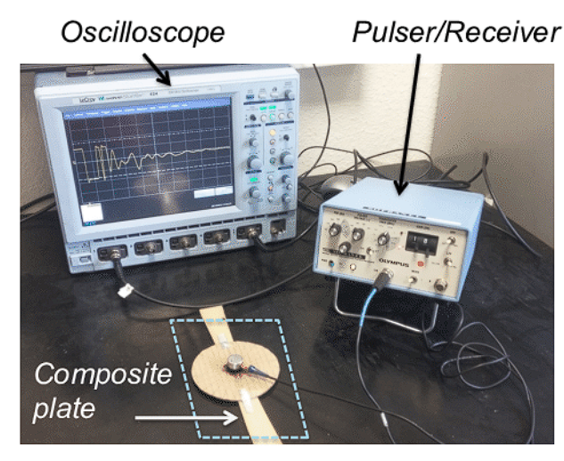
Oscilloscope paired with a Pulser/receiver for Digital signal analysis in an Ultrasonic Testing setup (image credits: Composites Part B: Engineering 142 (2018))
Also Read, Ultrasonic testing of Weld Joints.
Couplant:
This component is involved in the facilitation of the ultrasound waves being propagated through the test structure for effective flaw detection. Contact ultrasonic testing involves no distance between the test structure and the transducer since air has major attenuation effects on sound; a thin film of Glycerine, oil, or water is used as a Couplant.

A thin Fluid film used as a Couplant (Image credits: IOWA State University NDE-Ed)
In Immersion Ultrasonic testing, the fluid material surrounding the test structure acts as the Couplant, generally water.

Water Couplant in Immersion Ultrasonic testing (Image credits: IOWA State University NDE-Ed)
This form of coupling remains consistent with any movement in the transducer through the fluid medium, as both the test structure and the transducers are immersed, hence is a preference for immersion applications.
CAPABILITIES OF ULTRASONIC TESTING
Ultrasonic Testing is meritorious in flaw detection and provides consistently accurate data. Correct handling of the devices and thorough examination of the test subject makes it a highly preferred non-destructive testing method. The merits of the Ultrasonic Testing process are:
- The apparatus offers portability and can be used for laboratory and field use.
- Like every non-destructive method, this does not affect the operation of the test subject post-testing processes.
- This method of testing for flaws allows for deep analysis of the subject and permits the detection of flaws significantly below the surface of the test subject.
- The accuracy and responsiveness of the device are high, and it can be used to detect minute flaws present in the test subject as well.
- Ultrasonic Testing scans all test materials at the same rate, irrespective of their thickness.
- The digital tools and software provided with the testing apparatus make the testing process sublime and visually aid the operator in flaw detection and data management.
- This non-destructive testing method does not put the operator at risk and ensures safe handling.
- This process can be easily automated and used for large manufacturing units.
- The data obtained in this testing method is prompt and detailed for the operator to analyze.
USE OF ULTRASONIC TESTING FOR FLAW DETECTION
As mentioned in the previous sections, the Presence of flaws on the test surface is detected when diffraction is observed at the oscilloscope due to the waves reflected from the back surface and the flaws, respectively.
Once the defects have been detected, it is imperative to evaluate their size and overall dimensions. The methodology employed depends on the size of the beam width of the ultrasonic waves compared to the length of the defect. Suppose the defect size is smaller than the beam width. In that case, a reference reflector can be used for flaw signal amplitude comparison detected from the reflection, pseudo-sizing can be calculated, and decibel drop methods cannot be employed for precise measurements. For flaws bigger than the beam width, the maximum signals are detected at the extremities of the flaws by moving the transducer between the extremities, followed by using the decibel drop methods to estimate the flaw size using the data obtained.
INDUSTRY STANDARDS AND CODES FOR ULTRASONIC TESTING
AMERICAN STANDARDS AND INDUSTRY CODES
- American Society of Mechanical Engineers- Section VIII Division 1 – Pressure Vessel Construction – Ultrasonic Testing Inspection Services
- American Society of Mechanical Engineers- B 16.34 – Valves –
- Ultrasonic Testing● Straight Beam Examination
● Angel Beam Examination
- American Society of Mechanical Engineers- B 31.1 – Power Piping – Ultrasonic Testing
- American Society of Mechanical Engineers- B31.3 Process Piping – Ultrasonic Testing
- American Petroleum Institute-1104 Welding of Pipelines & Related Facilities – Ultrasonic Testing – Acceptance level
- American Welding Society- D1.1
- American Society of Testing and Materials- E164
- American Society of Testing and Materials- E213
- American Society of Testing and Materials- E587
- AS 2083: Calibration blocks for ultrasonic testing.
- AS 3998: Qualification of NDT personnel.
INDIAN STANDARDS AND INDUSTRY CODES
- Glossary of terms relating to ultrasonic testing (first revision)-2417: 1977
- Specification for calibration block for evaluation of ultrasonic flaw detection equipment (third revision )-4904: 1990
- The recommended procedure for ultrasonic examination of ferritic castings of carbon and low alloy steel (first revision )-7666: 1988
- Code of practice for non-destructive testing of steel castings 8780: 1978
- Recommended practice for certification of NDT person-9346: 1979.
- Acceptance Criteria for Ultrasonic Inspection of Steel Castings- IS 9565:1995
EUROPEAN STANDARDS
- EN 583-1: Non-destructive testing - Ultrasonic examination - Part 1: General principles.
- EN 583-2: Non-destructive testing - Ultrasonic examination - Part 2: Sensitivity and range setting.
- EN 583-3: Non-destructive testing - Ultrasonic examination - Part 3: Transmission technique;
- EN 583-4: Non-destructive testing - Ultrasonic examination - Part 4: Examination for discontinuities perpendicular to the surface;
- EN 583-5: Non-destructive testing - Ultrasonic examination - Part 5: Characterization and sizing of discontinuities;
- ENV 583-6: Non-destructive testing - Ultrasonic examination - Part 6: Time-of-flight diffraction technique for detection and sizing of discontinuities
- EN 12668-1: Non-destructive testing - Characterization and verification of ultrasonic examination equipment - Part 1: Instruments;
- EN 12668-2: Non-destructive testing - Characterization and verification of ultrasonic examination equipment - Part 2: Probes;
- EN 12668-3: Non-destructive testing - Characterization and verification of ultrasonic examination equipment - Part 3: Combined equipment.
- EN 1714: Non-destructive examination of welds - Ultrasonic examination of welded joints. (Will be ISO 17640).
- EN 1712: Non-destructive examination of welds - Ultrasonic examination of welded joints - Acceptance criteria (will be a new ISO work item);
- EN 1713: Non-destructive examination of welds - Ultrasonic examination - Characterization of indications in welds (will be a new ISO work item).
- EN 12062: Non-destructive examination of welds - General rules for metallic materials. (Will be ISO 17635).
- INTERNATIONAL ORGANIZATION FOR STANDARDIZATION
- ISO 12710: Non-destructive testing - Ultrasonic inspection - Evaluation of electronic characteristics of instruments;
- ISO 18175: Non-destructive testing - Evaluating performance characteristics of ultrasonic pulse-echo testing instruments without the use of electronic instruments;
- ISO 10375: Non-destructive testing - Ultrasonic inspection -Characterization of search unit and sound field;
- ISO 12715: Ultrasonic non-destructive testing - Reference blocks and test procedures for characterizing contact search unit beam profiles.
- ISO 9712: Non-destructive Testing - Qualification and certification of personnel.
- EN ISO 9000 series: Quality management and quality assurance standards - Guidelines;
- EN ISO/IEC 17025: General requirements for the competence of testing and calibration laboratories.
ACCEPTANCE CRITERIA FOR ULTRASONIC TESTING
As per Indian Standards -IS 9565: 1995, the acceptance criteria are as follows:
It is advised that the test subject to be examined under Ultrasonic Testing undergoes heat treatment so that the grain structure of the cast is broken down and refined. Austenitic steel castings like heat-resistant, high manganese casting and certain stainless steels are not considered favorable test subjects for Ultrasonic Testing processes. This is because, in such materials, the beam encountered has unusually high attenuation; hence special attachments and probes are used to analyze such material.
In the case of the examination of steel castings, as per the acceptance criteria IS 9565:1995, the casting is categorized into four zones, as follows:
- Zone 1:
includes the middle one-third of the thickness of the casting wall.
- Zone 2:
includes the outer and inner one-third wall thickness, which should equal or exceed 12 mm.
- Zone 3:
this is the region at 12mm from the surface of Zone 2
- Zone 4
includes the fabricated weld zone and the area that spans 25 mm along the casting length.
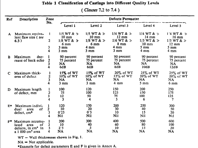
Classification of castings as per IS 9565:1995
The acceptance criteria state that in the case of heat-treated non-austenitic steel:
- For Samples with thickness less than or equal to 150 mm, the diameter of circular disc shape reflectors for point type indications will be 4mm, for indications with measurable extension will be 3mm, and the attenuation of back wall echo (using a 2MHz probe) should be 12dB.
- For Samples with thickness over 150mm up to 500mm, the diameter of circular disc shape reflectors for point type indications will be 6mm, for indications with measurable extension will be 3mm, and the attenuation of back wall echo (using a 2MHz probe) should be 12dB.
- For Samples with thickness in zone 4 and when the quality level is specified, the diameter of circular disc shape reflectors for point type indications will be 3mm, for indications with measurable extension will be 3mm, and the attenuation of back wall echo (using a 2MHz probe) should be 12dB.
The surface finish is required to be better than 12μm.
The ultrasonic testing operator should be qualified as per IS 9346:1979.
Samples with cracks, hot tears, and cold shuts are rejected.
Loss in back echo in ultrasonic testing without the speculation of flaws in the region under examination required further analysis using shear wave probes, radiographic scanning, or other approved methods.
For point defect indications, complete loss of back echo in the region of the flaw will be accepted.
If the defect spreads over two zones, the nearer surface is considered while acknowledging requirements. However, the previous assumption is considered invalid if the defect encroaches from an inner region to an outer region for a distance of ten percent of the wall thickness.
CONCLUSION
Non- destructive techniques used for structural testing have furthered humanity's reach beyond the scope of the physical senses crossing the constraints levied by the ever-growing industry and infrastructure. Ultrasonic testing is one of these gifts of modern sophistication to the field of flaw detection and defect Analysis giving unprecedented accuracy in the field, considered impossible employing conventional testing methods that humanity has relied on in maintaining structures that carry invaluable liability on loss.
Transducer probes used for Ultrasonic testing have been modified to fit myriad applications using robotics to carry out inspections with great accuracy and precision in the most remote and inhabitable regions ensuring elaborate data collection for test structures and shedding light on the causal factors and further prevention of the flaws.
The Ultrasonic Beamwidth is an important parameter as it provides a rough estimate for acceptable defect size, with defects smaller than the beam width only yielding an approximation of the size which is unreliable as the defects grow smaller than half the beam width. Accurate estimation is obtained with the techniques discussed for defects greater than beam width. Accurate testing and data estimation techniques have successfully assisted mankind in damage assessment and prevention, foundations for Modern Progress and development.


