Table of Content
- Introduction
- What is Alternating Current Field Measurement (ACFM)?
- The Principle of ACFM
- How an ACFM Inspection Is Carried Out
- Applications of ACFM
- Advantages of ACFM
- Limitations: What ACFM Cannot Do
- Quick Reference Tables
- Conclusion
- Frequently Asked Questions (FAQs)
Introduction
The ability to identify surface-breaking cracks prior to their becoming a critical failure is critical to the safety and reliability of industrial assets. Alternating Current Field Measurement (ACFM) is a sophisticated technique for electromagnetic non-destructive testing (NDT) that can be used to locate and measure surface cracks without removing coatings or calibration blocks. ACFM testing is commonly used in power, rail, offshore, oil & gas industries and is a rapid and dependable testing method for critical safety components, with minimal downtime.
What is Alternating Current Field Measurement (ACFM)?
Alternating Current Field Measurement (ACFM) is one of the electromagnetic non-destructive testing methods employed for the detection and sizing of surface-breaking cracks in conductive materials. No electrical contact required, can inspect through most non-conductive coatings, no calibration blocks required and will provide reliable measurements for crack length and depth.
Note: This article uses the term ACFM to mean Alternating Current Field Measurement and not Actual Cubic Feet per Minute, which is an airflow measurement found in HVAC and compressor systems.
Combining a principle of electromagnetic with a mathematical modelling, ACFM NDT is a method that is developed to inspect safety-critical structures for the presence of fatigue cracks and stress corrosion cracks. Unlike Magnetic Particle Inspection (MPI), which only provides a general indication of a crack, ACFM testing can also provide an estimate of the length and depth of a crack. This is because it can be used to inspect painted or coated surfaces with very little preparation, which is beneficial in industries where stripping paint or coatings is expensive or impractical.
The Principle of ACFM
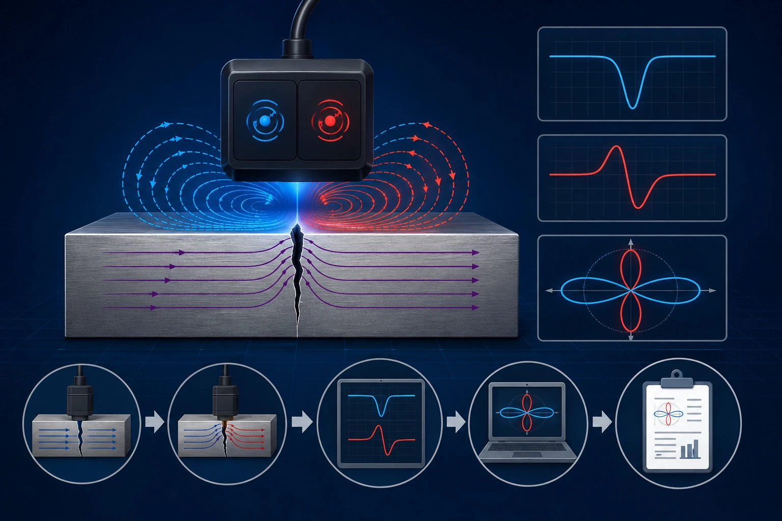
Both Alternating Current Field Measurement and conventional eddy current testing are based upon alternating electromagnetic fields, but they are based on different principles. Unlike the principle of localized eddy currents and measuring the impedance of a monitoring coil, the ACFM basic principle provides a uniform alternating current flow over the surface of a conductive component. The inspection system then measures the disturbance of this current and the magnetic field caused by a crack that is present on the surface of the component.
This is because of the skin effect – the alternating current is concentrated near the material's surface, so the method is very sensitive to any defect on the surface. When a crack is encountered the current can't just go through the crack, it must flow around the crack. This alteration of the current path introduces the predictable distortion of the magnetic field over the crack.
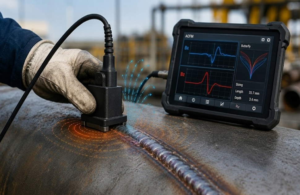
An ACFM probe measures two components of the magnetic field, Bx and Bz. The Bx signal can be used to detect the position and length of the crack, the Bz signal can highlight the crack tips with characteristic positive and negative peaks. These signals, when combined, create a unique butterfly plot for the inspector to confirm crack indications and give a better understanding of their characteristics.
The major benefit of ACFM NDT is that the crack sizing is performed using mathematical models that have been validated instead of calibration blocks. The inspection software uses analysis of the measured Bx and Bz signal to directly estimate the crack length and depth. The model-based approach minimizes the time required for set-up, provides greater repeatability and allows for reliable inspections of coated materials; alternating current field measurement is an attractive solution for weld inspections and other components where safety is paramount.
ACFM and conventional eddy current testing both rely on alternating electromagnetic fields but work differently — see how standard eddy current testing detects defects for comparison.
→ Read: Eddy Current Testing Explained
How an ACFM Inspection Is Carried Out
The ACFM inspection starts with choosing an appropriate probe based on the component geometry and requirements of the inspection. An ACFM instrument produces the alternating current and records the magnetic field signals created by it, connected to the probe. Generally a scan is preceded by an inspection of the equipment settings and the inspection surface being reasonably clean, but in most cases paint or protective coatings must not be removed.
The inspection is made by moving the probe at a steady speed across the weld or component surface and continuously measuring the components of the magnetic field (Bx and Bz). Today's ACFM systems show these signals in real time, so inspectors can track the area for indications of cracks as the scan proceeds. The data from the inspections is also stored in dedicated software and can be used to create butterfly plots, assess crack dimensions and create digital inspection reports.
This is the most common type of inspection and can be used for routine weld inspection as well as localized inspection. If the structure to be inspected is large or if it is a long weld, array probes can scan a larger area and increase the speed of the inspection. If transverse cracks are a potential problem, a second scan using the probe on the opposite angle may be conducted to assure that transverse cracks are detected.
Want to get certified in ACFM inspection? Check out the ACFM Level I course covering electromagnetic theory, probe operation, and signal interpretation for real-world inspections.
→ Read: Alternating Current Field Measurement (ACFM) Level I Course
Applications of ACFM
Alternating Current Field Measurement is commonly applied in industrial fields such as the case of surface breaking defects that might affect the integrity of the structure. It is particularly useful for in-service inspections, as it does not require extensive surface preparation to inspect through coatings.
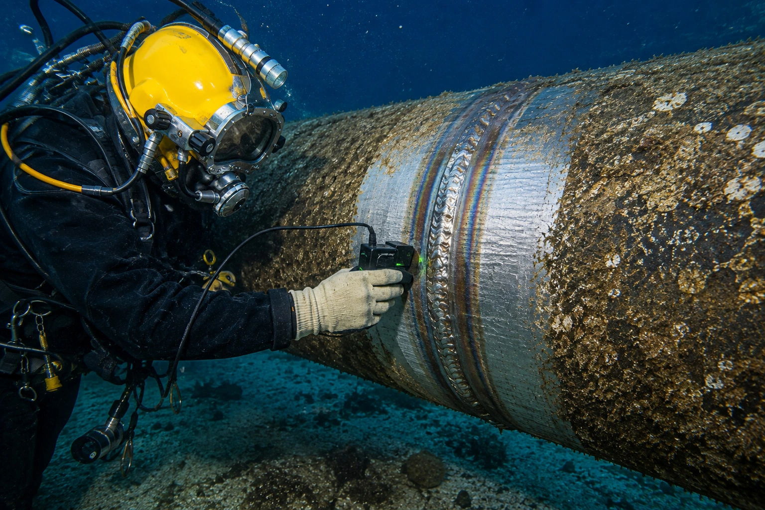
For welded structures, a typical application of ACFM testing would be to evaluate weld toes and heat-affected regions for fatigue cracking, which occurs during repeated loading conditions. It can be used for offshore platforms and subsea structures which have to be inspected underwater and the protective coatings removed, which is costly.
ACFM NDT is used in the oil and gas industry to detect fatigue cracks and stress corrosion cracking (SCC) in threaded connections, risers, pipelines, and pressure-containing components. It can be used in the railway industry to identify rolling contact fatigue in rail, switches and crossings before it becomes a safety concern. It can also be applied to assess the condition of tank cars, storage tanks, bridges and parts of power plants where early detection of cracking promotes preventive maintenance and avoids unplanned downtime. Also, dedicated ACFM equipment will make it possible to conduct high-temperature inspections, so that critical assets can be inspected while still in service.
Advantages of ACFM
The biggest benefit of ACFM is the capability to be able to examine through paint, protective coatings, light rust and scale, thus not requiring a lot of surface prep. This eases inspection time, decreases maintenance expenses and decreases disruptions to plant operations.
ACFM testing can not only identify cracks, but also estimate their length and depth — unlike many of the conventional inspection methods. This quantitative information aids the maintenance team to determine the severity of the defect and to decide on repairs. Because crack sizing is done mathematically, not by calibration blocks, inspections are easier to conduct and are more consistent.
Yet another advantage is that the technique is applicable for underwater, offshore and in-service inspections which may be challenging or impracticable with conventional inspection methods. Today's ACFM instruments also include real-time data visualization, permanent digital record and automated reporting, which make inspections more efficient and add to traceability for asset integrity management.
Unlike ACFM, Magnetic Particle Inspection only gives a general crack indication — learn how MPI works and where it's best applied.
→ Read: Magnetic Particle Testing
Limitations: What ACFM Cannot Do
Alternating Current Field Measurement (ACFM) is an effective electromagnetic inspection method, however, not all defects and materials can be inspected with ACFM. It is mostly used to identify surface discontinuities in the form of cracks, and is not as effective in finding subsurface or deeply embedded discontinuities.
The test is not suitable for detecting volumetric defects like porosity, slag inclusions or internal voids as these defects do not create the same surface current disturbances as open cracks can. It is also not capable of measuring the inclination or the angle of a crack and only can estimate its length and depth. Further, the performance of inspection depends on the material type, orientation of the probes and the surface condition. The practical detection capability is usually about 5 mm in crack length and 0.5 mm in crack depth, under favourable conditions. It is important that inspectors recognise these limitations, when choosing the most suitable NDT technique for a specific application.
Quick Reference Tables
Table 1. ACFM vs MPI vs Conventional Eddy Current Testing
Table 2. Common Applications of ACFM
Table 3. Typical Inspection Capabilities
*Actual detection capability depends on the material, probe type, surface condition, and inspection procedure.
Conclusion
Alternating Current Field Measurement (ACFM) is one of the most successful of the electromagnetic NDT methods for surface-breaking crack detection and sizing of safety-critical components. Its non-destructive ability to view through coatings, estimate crack size without calibration blocks, and provide permanently stored digital inspection records make it a preferred choice across a variety of industries, including the offshore, oil & gas, rail, power generation and heavy engineering sectors. ACFM NDT cannot detect volumetric defects but its rapidity, reliability and quantitative crack sizing for surface-breaking defects is an invaluable tool for preventive maintenance and asset integrity management.
Frequently Asked Questions (FAQs)
What is the smallest defect that ACFM can detect?
With favorable inspection conditions, ACFM testing may only be able to identify surface cracks around 5 mm long and 0.5 mm deep. The detection capability, however, will vary depending on the material, type of probe, surface condition, crack orientation and inspection procedure.
Can ACFM detect subsurface defects?
No, ACFM is specifically developed to measure the cracks on the surface. Insensitive to the detection of deep and volumetric defects like porosity, slag inclusions, laminations or internal voids. For such applications, techniques like Ultrasonic Testing (UT) or Radiographic Testing (RT) would be more suitable.
Is it possible to use ACFM under paint or with galvanised coatings?
Yes, One of the primary benefits of ACFM NDT is that many non-conductive coatings (such as paint and protective coatings) can be directly inspected without requiring removal. It works best with galvanised coatings, depending on the quality and thickness of the coating, and the inspection conditions, as specified by the equipment manufacturer.
How is ACFM different from Magnetic Particle Inspection (MPI)?
Both methods will pick up surface-breaking cracks, but Magnetic Particle Inspection (MPI) generally will show the existence of a defect. ACFM testing can, however, provide an estimation of the length and depth of a crack, create digital inspection records and can frequently be used to inspect through a protective coating, with limited surface preparation.
What certification is required to perform ACFM inspections?
Inspectors are usually trained and certified in such a manner as to be a member of an employer-based written practice or an employer certification scheme based on any of the standards, including ISO 9712 or ASNT SNT-TC-1A. Requirements for certification depend on the industry and/or regulatory requirements and the employer.
Which industries commonly use ACFM?
ACFM is used in the Offshore, oil & gas, marine, power generation, railway, petrochemical & heavy engineering industry. It especially works well in the examination of welded joints, pipelines, pressure vessels, storage tanks, threaded connections and other areas that may be prone to fatigue failure or stress corrosion cracking.