
Table of contents
- Introduction
- MT vs PT at a glance
- Magnetic particle testing (MT)
- Penetrant testing (PT)
- Process control and system checks
- Acceptance criteria by code
- Limits and common mistakes
- Key takeaways
- Frequently asked questions
- Related reading on OneStopNDT
- References
Introduction
Magnetic particle testing (MT) and penetrant testing (PT) are the most widely used surface NDT methods. Both look simple. Both depend on tight process control. This guide explains how each works, which checks keep them reliable, and how the main codes judge what they find.
MT and PT are often the first methods a new technician learns. They are cheap, portable and fast. They are also easy to get wrong. A weak magnetic field, a contaminated penetrant or a dim UV-A lamp can hide a crack completely. No alarm goes off.
That is why standards such as ASTM E1444 (MT for aerospace) and ASTM E1417 (PT) set out daily, weekly and periodic checks. It is also why acceptance criteria matter. Finding an indication is only half the job. The inspector must then judge it against the right code.
This guide covers both methods side by side. It explains:
- how each method works and where it fits
- the process steps and the system checks that keep them reliable
- how ASME, ISO, AWS and API acceptance criteria apply
- the most common mistakes
It ends with key takeaways, FAQs and a reference list.
MT vs PT at a glance
Magnetic particle testing (MT) | Penetrant testing (PT) | |
|---|---|---|
Materials | Ferromagnetic only: most carbon and low-alloy steels, and ferromagnetic iron, nickel and cobalt alloys (many nickel alloys are not ferromagnetic) | Nonporous metals and some nonmetals |
Not suitable for | Austenitic stainless steel, aluminum, titanium, copper and other nonmagnetic metals | Porous materials, such as some castings, unglazed ceramics and sintered parts |
Flaws found | Surface-breaking, and some slightly subsurface | Surface-breaking only (open to the surface) |
Key physics | Flux leakage at a discontinuity attracts magnetic particles | Capillary action draws liquid into the flaw; a developer draws it back out |
Best flaw orientation | Flaw at 90° to the magnetic flux; flaws up to about 45° are still shown | Any orientation, if the flaw is open and clean |
Coatings | Thin nonmagnetic coatings may be left on if the procedure demonstrates detection | Coatings must be removed; the flaw must be open |
Main process standards | ASTM E1444 (aerospace), E3024 (general industry), E709 (guide); ISO 9934 series | ASTM E1417, E165; ISO 3452 series; AMS 2644 materials |
Weld standards | ISO 17638 (method), ISO 23278 (acceptance) | ISO 3452-1 (method), ISO 23277 (acceptance) |
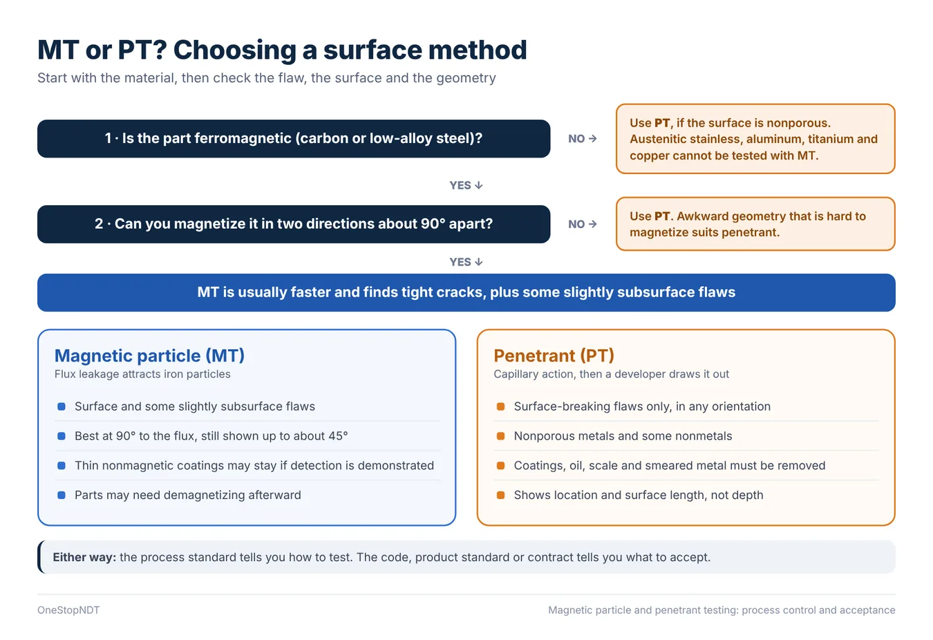
A simple rule. If the part is ferromagnetic, MT is usually faster and finds tight cracks and some slightly subsurface flaws. If it is not, or the geometry makes magnetizing difficult, use PT.
Magnetic particle testing (MT)
How it works
MT magnetizes a ferromagnetic part. Where a crack or other discontinuity crosses the magnetic flux, some flux leaks out of the surface. Fine iron particles applied to the surface gather at this leakage field and form a visible line, called an indication.
Think of the part as a pipe carrying water. A crack is like a break in the pipe wall: water sprays out exactly where the break is. The particles show where the flux “sprays out.”
The flaw shows best when it lies at 90° to the flux. TWI notes that flaws up to about 45° to the flux lines will still be shown. This is why every area must be magnetized in two directions about 90° apart.
Ways to magnetize
TWI lists the common techniques:
- Portable: electromagnetic yokes, permanent magnets, current-flow prods, flexible coils and adjacent cables.
- Bench units: head shots (current through the part), central conductors (threading bars), fixed coils, magnetic flow and induced current.
A coil makes a longitudinal field along the part, which shows transverse cracks. Passing current through the part or a central conductor makes a circular field, which shows longitudinal cracks.
The type of current also matters. Alternating current (AC) concentrates the field at the surface. Rectified direct current (half-wave or full-wave DC) gives more penetration for slightly subsurface flaws.
Particles
Particles are dry (powder) or wet (suspended in oil or water), and visible (colored) or fluorescent (viewed under UV-A light). ASTM E1444, the aerospace practice, is written mainly around the wet fluorescent method.
Checking that the field is adequate
Current settings alone do not prove a part is magnetized correctly. Common checks include:
- Quantitative quality indicators (QQIs). These are small shims with artificial flaws, placed on the part. They show field direction and adequate strength. They have been mandatory in E1444 since 2005, and their design is set by SAE AS5371.
- Pie gauges and Berthold penetrameters. These show field direction only. Magnaflux notes they are not adequate for showing field strength.
- Yoke lift test. An AC yoke must lift a 10 lb (4.5 kg) test weight. DC yoke requirements differ by standard. ASME V Article 7 is reported as 40 lb (18 kg) at the maximum pole spacing used. E709 and E1444 are reported as 30 lb (13.6 kg) at 2–4 in. or 50 lb (22.7 kg) at 4–6 in. Always state the lift value together with the pole spacing.
Demagnetization
Residual magnetism can attract metal debris, affect machining or welding, or disturb instruments. Parts are demagnetized after inspection when the specification requires it. Under E1444, parts must be inspected before demagnetization. Many specifications set a maximum residual field of about 3 gauss (0.24 kA/m), but the limit depends on the customer and the standard.
Penetrant testing (PT)
How it works
A penetrant is a low-viscosity liquid that soaks into open surface flaws by capillary action. After a set time, called the dwell time, the excess is removed from the surface. A developer is then applied. It acts like blotting paper, drawing the trapped penetrant back out to form a visible indication that is wider than the flaw itself.
PT only works if the flaw is open to the surface and clean. Paint, oil, scale or smeared metal over a crack will block the penetrant. PT is limited to nonporous materials.
Types, methods and sensitivity levels
Penetrant systems are classified under SAE AMS 2644:
Classification | Options |
|---|---|
Type | Type 1: fluorescent (viewed under UV-A) · Type 2: visible (colored, usually red) |
Method (how excess is removed) | A: water-washable · B: post-emulsifiable, lipophilic · C: solvent-removable · D: post-emulsifiable, hydrophilic |
Sensitivity level (Type 1 only) | ½ (ultra-low), 1 (low), 2 (medium), 3 (high), 4 (ultra-high) |
Developer form | a: dry powder · b: water-soluble · c: water-suspendable · d: nonaqueous for Type 1 · e: nonaqueous for Type 2 |
ASTM E1417-21 added Method A(W). This is a water-washable penetrant that contains 20% or more water by volume per AMS 2644.
Two common errors are worth correcting here. First, “dye penetrant” is not only red visible dye: fluorescent (Type 1) penetrants are generally the more sensitive family, and formal sensitivity levels apply only to them. Second, “water-washable” does not mean “water-soluble”: Method A penetrants have a built-in emulsifier, so they rinse off with water without a separate emulsifier step.
Process steps
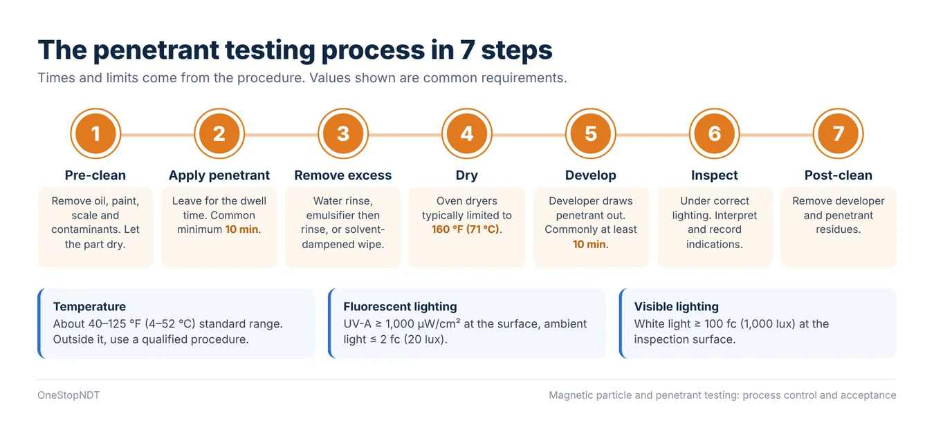
- Pre-clean the surface, removing oil, paint, scale and other contaminants, and let it dry.
- Apply penetrant and leave it for the dwell time set by the procedure. A common minimum is 10 minutes.
- Remove excess penetrant using the method’s process: water rinse, emulsifier then rinse, or solvent-dampened wipe.
- Dry the part. Oven dryers are typically limited to 160 °F (71 °C).
- Apply developer and wait for the development time. A common requirement is at least 10 minutes, with a maximum set by the procedure.
- Inspect under the right lighting (see the next section), then interpret and record indications.
- Post-clean the part.
Temperature matters. ASTM E1417 and ASME Section V Article 6 both use about 40 to 125 °F (4 to 52 °C) as the standard range. Outside it, a qualified procedure is needed. ISO 3452-5 and ISO 3452-6 cover PT above 50 °C and below 10 °C.
For soft metals such as aluminum, machining can smear metal over a crack and close it. Aerospace procedures such as NASA PRC-6506 require smeared metal to be removed, by etching or electropolishing, before final penetrant inspection. That procedure exempts as-cast weld and additively manufactured surfaces.
Process control and system checks
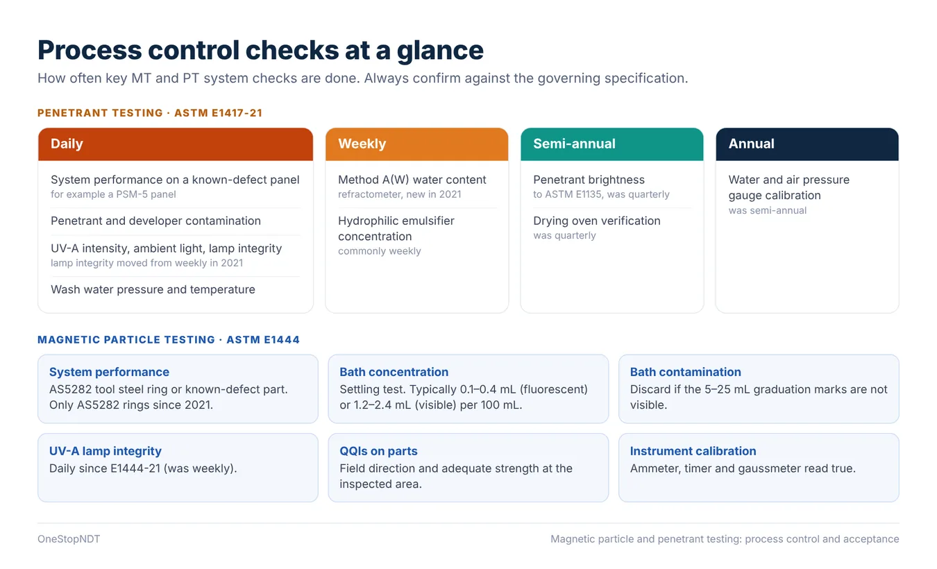
MT and PT are only as good as their process control. A crack that is present but not shown gives no warning. The checks below are how a shop proves its system can still find the flaws it is meant to find.
Lighting
Both methods depend on the inspector seeing the indication, so lighting is checked often. Typical requirements:
- Fluorescent (Type 1 PT, fluorescent MT). UV-A irradiance of at least 1,000 µW/cm² at the inspection surface, and ambient visible light of 2 foot-candles (20 lux) or less.
- Visible (Type 2 PT, visible MT). White light of at least 100 foot-candles (1,000 lux) at the surface.
- Lamp wavelength. UV-A is defined as 320 to 400 nm in ASTM E2297. Fluorescent materials are tuned to the 365 nm mercury line. A Magnaflux specialist reports that E3022 requires LED lamps to peak between 360 and 370 nm.
- Warm-up. Under ASTM E1417-21, non-LED UV-A lamps need at least 10 minutes’ warm-up. LED lamps are exempt.
- Dark adaptation. Inspectors need time in the dark booth before inspecting. ASME Section V is cited as requiring at least 5 minutes.
ASTM E2297 covers UV-A and visible-light meters. ASTM E3022 covers LED UV-A lamp emission. ISO 3059 covers viewing conditions under ISO practice.
MT system checks
Check | What it shows | Standard |
|---|---|---|
System performance on an AS5282 tool steel ring or a known-defect part | That the whole system still finds a known flaw. Since 2021, E1444 accepts only AS5282 rings | SAE AS5282; ASTM E1444 |
Bath concentration (settling test in a centrifuge tube) | Particle concentration is in range. Typical ranges are 0.1–0.4 mL per 100 mL for fluorescent and 1.2–2.4 mL per 100 mL for visible particles | ASTM E1444; ASTM E709 |
Bath contamination and clarity | Oil, water or dirt in the bath. Under E1444-21, discard the bath if the graduation marks between 5 and 25 mL on the tube are not visible | ASTM E1444-21 |
UV-A lamp integrity | Damaged filters let harmful light through. E1444-21 moved this check from weekly to daily | ASTM E1444-21 |
QQIs on parts | Field direction and adequate strength at the inspected area | SAE AS5371 |
Ammeter, timer and gaussmeter calibration | That indicated current and time are true | ASTM E1444 |
PT system checks
Check | Frequency under E1417-21 (where verified) | Standard |
|---|---|---|
System performance on a known-defect panel, such as a TAM 146040 (PSM-5) panel | Daily | ASTM E1417 |
Penetrant contamination; developer contamination (dry developer: replace at 10 or more fluorescent specks in a 10 cm circle) | Daily | ASTM E1417 |
UV-A intensity, ambient light, UV lamp integrity | Daily (lamp integrity moved from weekly in 2021) | ASTM E1417-21 |
Wash water pressure and temperature | Daily | ASTM E1417 |
Method A(W) water content (refractometer) | Weekly (new in 2021) | ASTM E1417-21 |
Hydrophilic emulsifier concentration (refractometer) | Commonly weekly; confirm in E1417-21 Table 1 | ASTM E1417-21 |
Penetrant brightness (to ASTM E1135) | Semi-annual (from quarterly in 2021) | ASTM E1417-21; ASTM E1135 |
Drying oven verification | Semi-annual (from quarterly) | ASTM E1417-21 |
Water and air pressure gauge calibration | Annual (from semi-annual) | ASTM E1417-21 |
Common PT process limits for Method A rinsing are water pressure below 40 psi (275 kPa) and temperature of 50 to 100 °F (10 to 38 °C).
Acceptance criteria by code
The process standards above tell you how to test. They do not tell you what to accept. ASTM E165 and ISO 3452-1, for example, contain no acceptance criteria. Acceptance comes from the construction code, the product standard or the contract.
Key terms
- Indication: the visible evidence of particles or penetrant.
- Relevant indication: one caused by a real discontinuity and large enough to evaluate.
- Nonrelevant indication: a real indication from geometry or a magnetic change, such as a keyway or a change in section.
- False indication: one caused by poor technique, such as poor rinsing or fingerprints.
- Linear vs rounded: in ASME VIII Div. 1, a linear indication has a length more than three times its width. Otherwise it is rounded.
ASME BPVC Section VIII, Division 1
Mandatory Appendix 6 (MT) and Appendix 8 (PT) use the same acceptance standard. The acceptance standards are:
Rule | Requirement |
|---|---|
Relevant indications | Only indications with a major dimension greater than 1/16 in. (1.5 mm) are relevant |
Reject | Any relevant linear indication |
Reject | Relevant rounded indications greater than 3/16 in. (5 mm) |
Reject | Four or more relevant rounded indications in a line, separated by 1/16 in. (1.5 mm) or less, edge to edge |
ASME B31.3 (process piping)
B31.3 sets weld acceptance in Table 341.3.2. The 2024 edition revised the acceptance criteria for surfaces where attachment welds have been removed. Check the MT and PT limits in the current edition of the code before applying them to a job.
AWS D1.1/D1.1M (structural steel)
The current edition is D1.1/D1.1M:2025, released in April 2025. Under clause 8.10, welds examined by MT or PT are judged against the visual inspection criteria of Table 8.1.
API 1104 (pipeline welding)
The current edition is the 22nd (2021, with Errata 1 of 2023). For regulated US pipelines, PHMSA still incorporates the 21st edition by reference. API 1104 has its own MT and PT acceptance rules, which differ from ASME. A common error on the web is to quote API 1104 values as “ASME.”
ISO weld standards
ISO 23278:2015 sets acceptance levels for MT of ferromagnetic steel welds. ISO 23277:2015 sets them for PT of metallic welds. The test methods themselves are ISO 17638 (MT) and ISO 3452-1 (PT). Each standard grades several acceptance levels. ISO 17635 shows how they relate to the weld quality levels of ISO 5817 (steel) and, for ISO 23277, ISO 10042 (aluminum).
Practical rule. Before testing, write down which code, edition and acceptance level apply. Record them on the report.
Limits and common mistakes
Limits of MT
- Ferromagnetic materials only. It will not work on austenitic stainless steel, aluminum, titanium or copper alloys.
- It finds surface and slightly subsurface flaws only. It does not replace ultrasonic or radiographic testing for deep flaws.
- A flaw parallel to the flux may not show, so two magnetizations at about 90° are needed.
- Parts may need demagnetizing afterward.
Limits of PT
- It finds only flaws open to the surface.
- It does not work on porous materials.
- Smeared metal, paint, oil or scale can close a flaw. Soft machined metals may need etching or electropolishing first.
- Indications show where a flaw is and how long it is at the surface. They do not show depth.
Mistakes seen in published content and in practice
- Claiming MT works on austenitic stainless steel. It does not.
- Claiming PT works on porous surfaces. It does not.
- Quoting a single “standard” dwell or development time. Times are set by the procedure and the materials.
- Using pie gauges to prove field strength. They show direction only.
- Treating a process standard (E1417, E1444) as the source of acceptance criteria.
- Quoting API 1104 criteria as ASME criteria.
Key takeaways
- MT works only on ferromagnetic materials and finds surface and slightly subsurface flaws. PT works on any nonporous material but finds only surface-breaking flaws.
- Both methods rely on process control: lighting, system performance checks and consumable checks are done daily, weekly or at set intervals.
- Fluorescent inspection needs at least 1,000 µW/cm² UV-A and no more than 2 fc (20 lux) ambient light.
- Process standards tell you how to test; codes such as ASME VIII, AWS D1.1, API 1104 and ISO 23277/23278 tell you what to accept.
- Check the edition. ASTM E1444 (2026), E1417 (2021) and ASME (2025) have all changed recently.
Frequently asked questions
Can magnetic particle testing be used on stainless steel?
Only on ferromagnetic grades. ASTM E1444 excludes nonferromagnetic metals such as austenitic stainless steel. Use PT or eddy current testing on those.
Which is more sensitive, MT or PT?
It depends on the part and the flaw. MT can find some slightly subsurface flaws that PT cannot. PT works on more materials. For fluorescent PT, sensitivity is graded from level ½ to level 4.
What UV-A intensity is required for fluorescent inspection?
A common minimum is 1,000 µW/cm² at the inspection surface, with ambient light no more than 2 fc (20 lux). Always check the governing specification.
What is the dwell time for penetrant testing?
It is set by the procedure and the penetrant manufacturer. Ten minutes is a common minimum at normal temperatures.
What is the difference between Type 1 and Type 2 penetrant?
Type 1 is fluorescent and is viewed under UV-A light. Type 2 is visible, usually red, and is viewed under white light.
What are the ASME acceptance criteria for MT and PT?
Under ASME VIII Div. 1, Appendices 6 and 8, relevant linear indications are rejected. So are rounded indications over 3/16 in. (5 mm) and four or more rounded indications in a line spaced 1/16 in. (1.5 mm) or less.
Why must parts be magnetized in two directions?
A flaw shows best at 90° to the flux and may be missed if it runs parallel to it. Two magnetizations about 90° apart cover all orientations.
Is certification for MT and PT the same as for other methods?
Yes. MT and PT are separate methods under ISO 9712 and ASNT schemes, each with Levels I, II and III.
- Magnetic particle testing: the complete guide
- Liquid penetrant testing: the complete guide
- Penetrant testing system performance and maintenance
References
- ASTM, E1444/E1444M-26, Magnetic Particle Testing for Aerospace (2026)
- ASTM, E1417/E1417M-21e1, Liquid Penetrant Testing (2021)
- ASTM, E165/E165M-23, Liquid Penetrant Testing for General Industry (2023)
- TWI, What are the principles of magnetic particle inspection? (2016)
- TWI, How do we ensure defects of all orientations are detected? (2016)
- SAE, AMS2644J, Inspection Material, Penetrant (2024)
- Magnaflux, ASTM E1417 updates (2021)
- ISO, ISO 9934-1:2016, MT general principles
- ISO, ISO 3452-1:2021, PT general principles
- E. Pompa, ASNT, Proper use of quantitative quality indicators (2023)
- SAE, AS5282C, Tool Steel Ring for MPI (2023)
- Magnaflux, 9 daily performance checks for LPI systems (2018)
- ASTM, E2297-23, UV-A and visible light sources and meters (2023)
- ISO, ISO 23277:2015, PT of welds: acceptance levels
- ISO, ISO 23278:2015, MT of welds: acceptance levels
- ASME, BPVC Section V, 2025
- AWS, AWS announces release of D1.1/D1.1M:2025 (2025)
- ISO, ISO 9712:2021
There are no comments yet!