
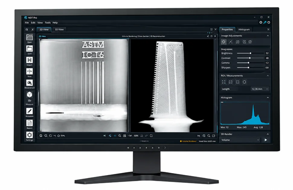
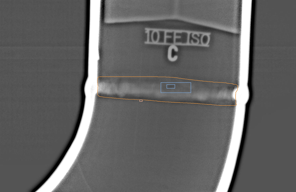
Image source: DÜRR NDT
Table of content
- Why DR Needs More Proof Than Film
- The Three Standards in One Line Each
- Detector Qualification
- SNR and Basic Spatial Resolution
- Procedure Demonstration
- Records
- Quick Summary
- Sources
When you move from film to DR, you have to prove four things: your detector works, your images are clear enough, your procedure has been tested, and your image files are kept safe. This article outlines each of these in simple terms.
Why DR Needs More Proof Than Film
Film included a high level of quality control. The film manufacturer guaranteed the film class. Using a density meter, your team determined the density. The shot was successful if the density was accurate and the IQI wire or hole showed up.
That is not the case with a digital detector. It’s an electrical panel that resembles a large camera sensor. You have control over the following factors that affect its image quality:
- how the panel is calibrated.
- how many pixels have failed.
- how long you expose the image.
- what software settings were used.
None of this is visible on the screen, so the standards require you to measure it, record it and review it at a later time.
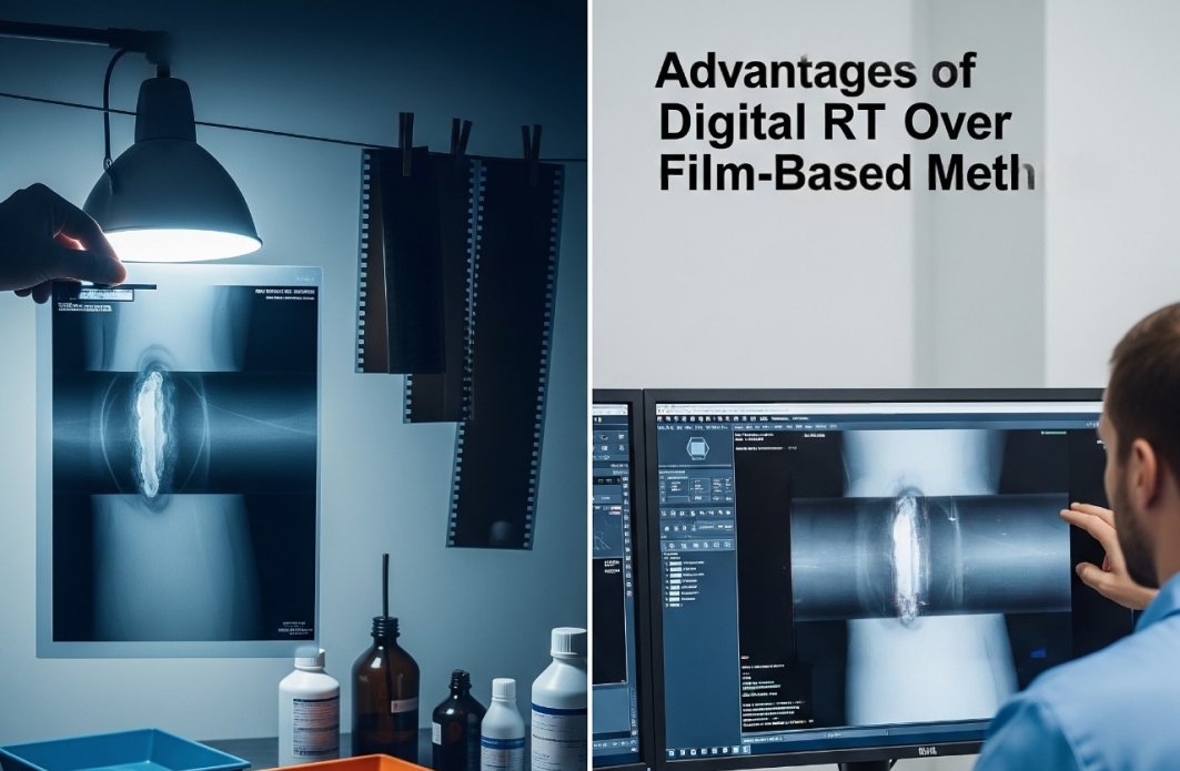
Film needed no detector qualification, and DR does. Here’s the complete comparison of digital and film radiography and what changes when you switch.
→ Read: Digital vs Film Radiography: Advantages
The Three Standards in One Line Each
- For work involving ASME codes (pressure vessels, boilers, pipes), refer to ASME Section V, Article 2. The main article contains the rules for film radiography. The digital detector requirements in Mandatory Appendix IX are an addition to the film rules.
- ISO 17636-2:2022 covers digital weld radiography under ISO or EN requirements. It offers the most accurate target numbers for shooting.
- A standard for digital detector arrays, ASTM E2698-26 is frequently used in aerospace and in contracts that specifically cite ASTM. It is always used with ASTM E2737, which covers detector testing.
Your customer’s code or contract determines which one applies. Make sure you get written approval that digital (Appendix IX) is allowed before starting if the contract just specifies “Article 2.”
These docs don’t say whether a weld passes. Construction codes, such as ASME Section VIII or ISO 10675, are the source of acceptance criteria.
Detector Qualification
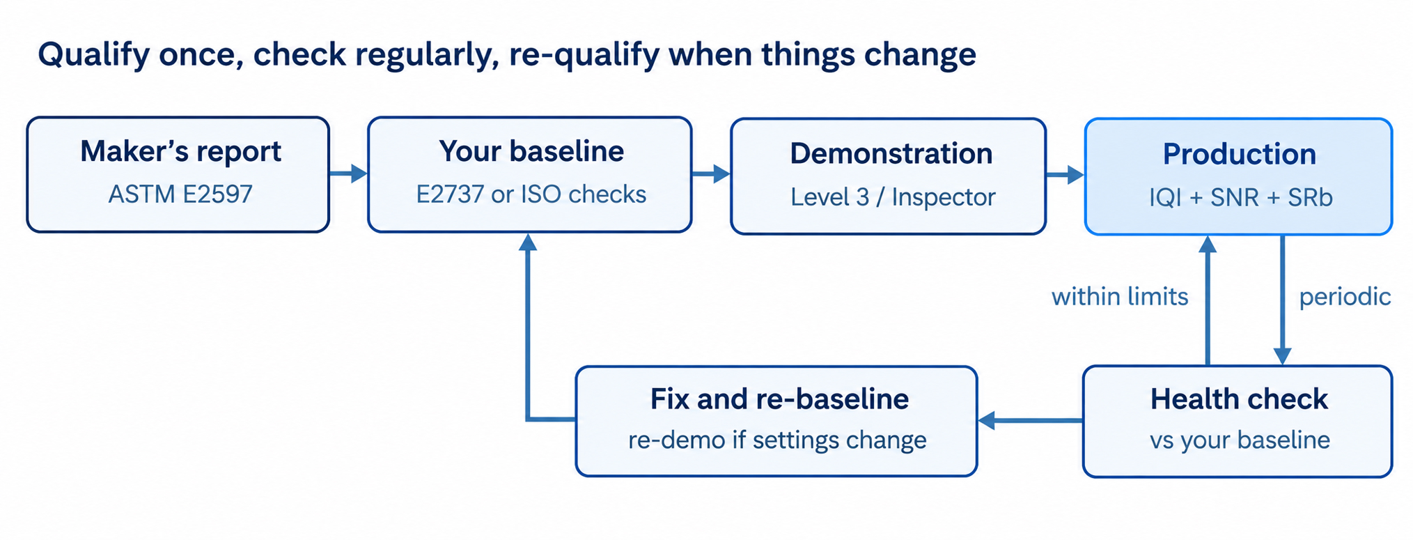
Detector qualification involves demonstrating that your specific panel, identified by its serial number, performs as expected — at the time of delivery and throughout the life of the detector.
Consider it in three steps.
Step 1: Manufacturer’s Test Report
The detector manufacturer conducts tests on the model following the guidelines set forth in ASTM E2597 and provides the key numbers: sharpness, sensitivity, and the definition of a bad pixel. To select a detector suitable for your thicknesses, you can use this report.
The steps to take: request the E2597 report for your exact model and firmware from the supplier. A sales brochure isn’t sufficient.
Step 2: Your Own Starting Point (Baseline)
Upon arrival of the panel, test the panel and record results. This is the “healthy” reading and will serve as a reference for the remainder of its life.
- ASTM E2698 says this baseline must be done to ASTM E2737. E2737 uses two simple test pieces (a duplex plate and a five-groove wedge) and instructs you which measurements to take.
- ISO 17636-2 does not reference E2737, but asks for the same fundamental elements in its own language:
- Use a dark image and at least one evenly exposed image to calibrate the panel as per manufacturer’s instructions. These calibration images should be at least twice the dose of a normal shot.
- Identify the bad pixels and save the map. Avoid panels with clusters of bad pixels in the area you need to read.
- Measure sharpness with a duplex wire IQI placed directly on the panel under given conditions (e.g. 160 kV, 1 mm copper filter, steel up to 20 mm).
The ASME Appendix IX also requires that the panel be calibrated according to the manufacturer’s instructions and tested prior to production use. Review your copy of the code for the precise wording.
Step 3: Regular Health Checks
The panels will deteriorate over time. With a large amount of radiation, the pixels fail, the response drifts or the scintillator layer loses efficiency. Regular checks with the baseline determine whether or not the panel is still fit for use.
What to do:
- State in your procedure how often you will re-test (e.g., monthly or quarterly).
- Set the limit at which a panel is taken out of service.
- Re-calibrate if exposure conditions are significantly different, and re-check bad pixels often.
- Repeat the baseline after any repair or firmware upgrade.
Keep every result. A simple trend chart of these numbers is one of the first things a good auditor will ask to see.
SNR and Basic Spatial Resolution
In DR, two numbers replace the function of the film density. SNR indicates if the image was properly exposed. Basic spatial resolution (SRb) is an indicator of the amount of detail the system can display. You still need the IQI to show up as well.
SNR in Plain Words
SNR is the ratio between the signal and the noise. All digital pictures contain some “noise” (like static on a radio). The higher the SNR, the clearer the image, and the easier it is to detect small thickness changes.
The easiest way to increase SNR is to increase the exposure time, number of frames or tube current for the panel.
There is one catch. If the detector is blurry, a high SNR may be simply due to the blurriness. This is why ISO 17636-2 uses normalized SNR (SNRN). It adjusts the SNR for the detector’s sharpness (SRb), which means that a fuzzy panel isn’t able to “cheat”. It is usually calculated once you type in the SRb value in your viewing software.
Basic Spatial Resolution in Plain Words
SRb answers the question: ‘What is the smallest detail this system can separate?’ This is measured by a duplex wire IQI: pairs of fine wires that get thinner and closer together. Find the first wire pair that blurs into a single line. Half of that blur is the SRb which is in millimetres.
- The duplex is positioned on the panel and the sharpness of the detector is measured.
- It is placed on the part (source side), and the sharpness of the actual image is measured, including that of source size and distance blur.
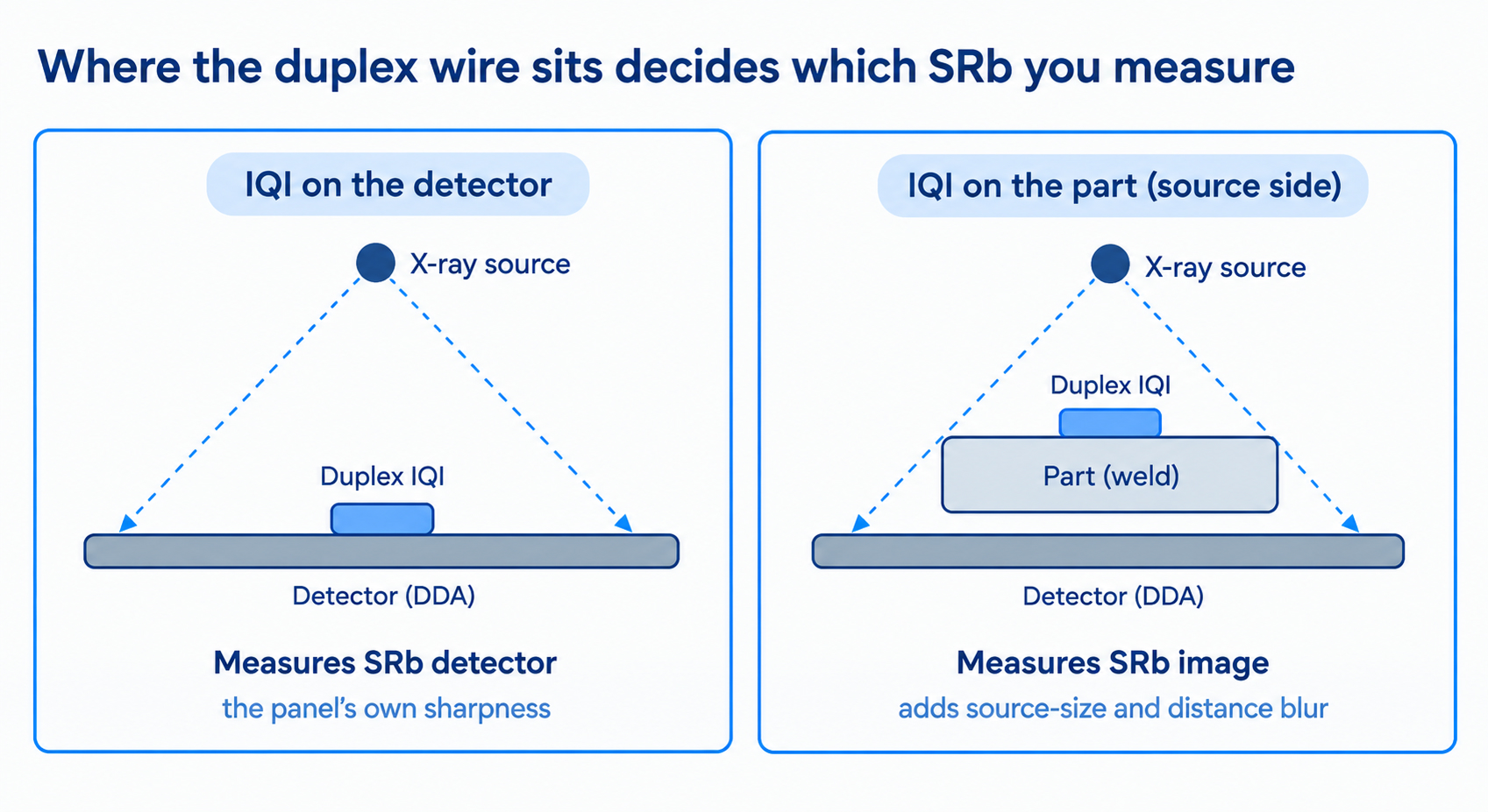
A smaller SRb number means a sharper image.
What ISO 17636-2 Asks For
ISO 17636-2 gives exact targets (ISO 17636-2:2022, Table 3 and Annex B). For steel, these are the minimum SNRN values when measured in the weld:
Radiation source | Class A (basic) | Class B (improved) |
|---|---|---|
X-ray 50–150 kV | 70 | 120 |
X-ray 150–250 kV | 70 | 100 |
Ir-192 or Se-75, up to 50 mm | 70 | 100 |
If you measure next to the weld instead of in it, the target is 1.4 times higher.
For sharpness, the standard sets a maximum SRb for each thickness. For example, class B steel 4–8 mm needs a duplex pair D12 (SRb 0.063 mm). Steel 12–40 mm needs D10 (SRb 0.10 mm).
If your detector is not sharp enough, ISO allows a trade-off called compensation principle II. For each duplex wire pair you cannot see, you must see one extra, finer single wire on the normal IQI — up to three. In simple terms, a cleaner image can make up for a slightly blurrier one.
What ASTM E2698 Asks For
E2698 does not provide a single table for each job. Instead, you will test your entire system to its intended use and complete a system qualification report. SNR, contrast and sharpness are compared with your E2737 baseline. Generally the precise targets are set by the customer or engineering authority.
What ASME Asks For
ASME keeps its film-based approach. The decision regarding the hole or wire which must be visible is still made through the IQI tables from Article 2. Digital checks are placed on top of the above controls in Appendix IX including a duplex wire or line-pair sharpness check. Check whether your edition sets a fixed SNR minimum; if it does, copy it into the procedure word for word.
One Rule for All Three
Check the raw image (calibrated but not sharpened or filtered) for image quality. ISO 17636-2 requires this, and it is good practice under all three. If there is a filter used to read welds then read the IQI using the same filter settings.
SNR and CNR are easy to confuse, and each one answers a different question. Here’s the complete guide to what radiological technologists need to know about both.
→ Read: CNR vs SNR: What Radiological Technologists Need to Know
Procedure Demonstration
A procedure demonstration is a trial of the procedure. You practice your written DR procedure using actual or representative parts and demonstrate that all images comply with the image-quality rules. Only then can it be applied to the production work.
A common error is using the old film procedure, but changing the term “film” to “detector”. That will not pass an audit. DR has its own settings, and they must be written down.
What Each Standard Expects
- ASME: Your procedure contains “essential variables,” settings that have an impact on the quality. If one is changed, the procedure must be demonstrated again. Where the construction code requires it, the demonstration must satisfy the Authorized Inspector before production starts. For DR, consider these as essential: detector model, pixel size, software and version, calibration method and image processing.
- ASTM E2698: You create a procedure for your application, and your Level 3 will have to approve your procedure before you check any parts made in production. The proof that it works is your system qualification report.
- ISO 17636-2: There is no formal demonstration clause. The technique and testing class are agreed with the customer, and all pictures are required to pass the IQI, SNRN and sharpness tests. Inspectors must have ISO 9712 certification in addition to further training in digital radiography. In reality, most of the time, the customer still wants to witness a demonstration.
How to Run the Demonstration
- Freeze the settings. Record the detector & serial number, software version, calibration method, exposure time and numbers of frames, kV and mA (or source), distances, filters and image processing.
- Select the more challenging cases. Test the thinnest and thickest material you are going to use the procedure with and the most challenging setup you can get (e.g. the smallest pipe diameter).
- Shoot like production. Use the same IQIs in the same positions that you will find on the job. Record IQI, SNR and SRb.
- Read on the actual monitor. Use the same screen, room light as you will during production. For instance, ISO 17636-2 requires that the screen be bright with high contrast in a dark room.
- If available, use samples with known flaws. A visible IQI wire does NOT guarantee you can see a fine crack.
- Get it signed. Your Level 3 signs the package. It is accepted by the Inspector under ASME if the code requires it.
When to Demonstrate Again
Include these triggers in the procedure so there is no debate later:
- new detector model/replaced panel;
- upgrade of firmware or software;
- new calibration method or new image filters;
- change of radiation source or radiation energy range;
- results of detector health checks fall outside the limits.
Records
When using film, the record was the radiograph. For DR, the record will consist of the original image file and the information about how the picture was captured and read. Without both, you have a picture, not an inspection result.
Keep the Original Image
ISO 17636-2 is the clearest on this:
- Keep the original image at the detector’s full resolution.
- Only calibration corrections (dark image, gain and bad-pixel correction) may be applied before saving.
- Only use lossless compression. Never save the record as a JPEG.
- Have more than one copy, and a long-term backup plan.
- If you’re using filters to view the image, be sure to document the settings for it so that anyone else can duplicate them.
The intent of ASME and ASTM E2698 is the same: retain the original image, document any processing and have access to both for as long as the construction code requires. It’s easier for customers to share images in a standard file format like DICONDE.
What Goes in Each Inspection Report
In addition to the standard information (part, material, thickness, technique, source, IQI results), a DR report should include the following:
- detector type and settings: gain, frame time, number of frames, pixel size and calibration method;
- the sharpness of the detector (SRb) and any magnification applied;
- required and achieved SNR or SNRN;
- required and achieved IQI values and their location;
- the image-processing or filter settings;
- software used to evaluate the image;
- name, certification and signature of the person who read it.
Records Behind the Reports
Auditors now ask for the evidence that sits behind each report. Keep a file with:
- the manufacturer’s E2597 report;
- all of your baseline (E2737 or equivalent) and all health-check results;
- the current bad-pixel map, with its date;
- calibration records;
- the procedure demonstration package and approvals;
- monitor check records;
- inspector certificates, including digital training;
- a history of the software and firmware versions used.
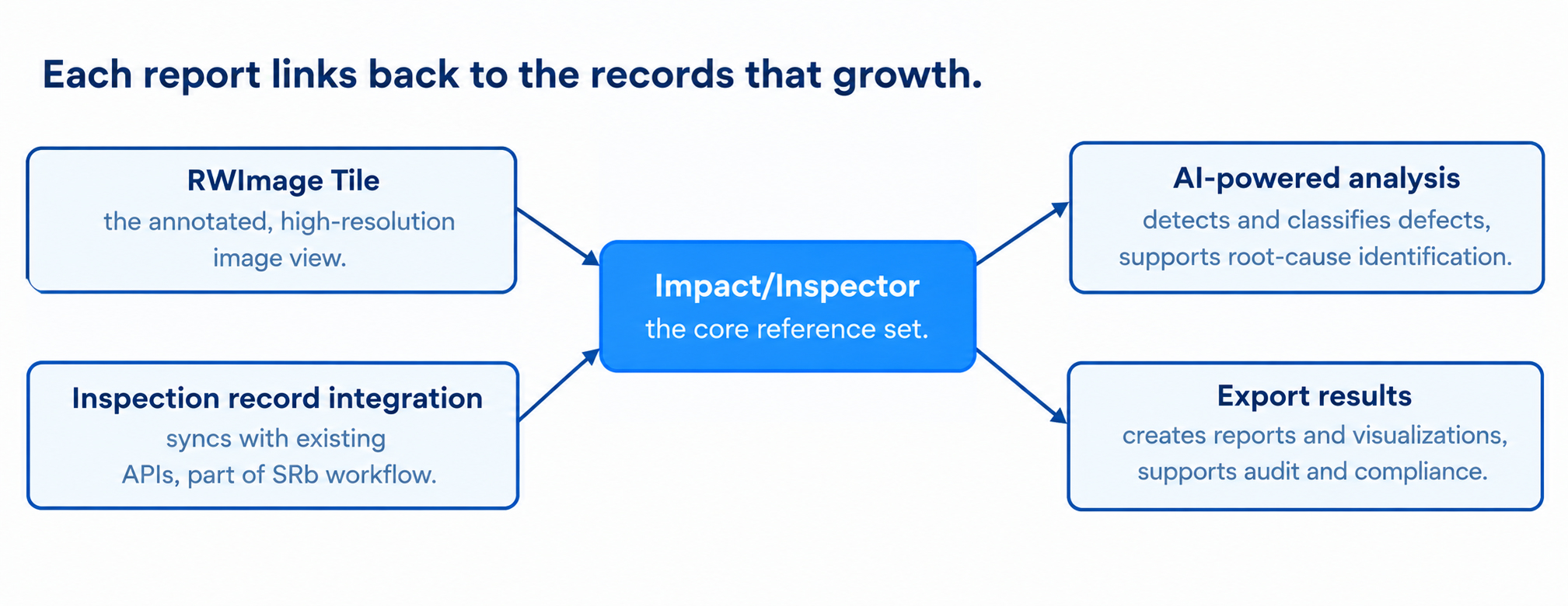 Provide a link between each inspection report and the corresponding calibration and health-check reports which were in effect on the day of the exposure. That is the link that enables you to defend an image years later.
Quick Summary
In short: ISO 17636-2 gives you exact numbers to hit, ASTM E2698 gives you a system to qualify, and ASME keeps its film rules and adds digital checks on top.
Topic | ASME V Art. 2 + App. IX | ISO 17636-2:2022 | ASTM E2698-26 |
|---|---|---|---|
Detector qualification | Calibrate per manufacturer; check before use | Calibrate, map bad pixels, measure sharpness | E2737 baseline required |
SNR | Check your edition | Fixed minimums (70–150) | Set during system qualification |
Sharpness (SRb) | Duplex wire or line-pair check | Maximum per thickness; trade-off allowed | Measured against baseline |
Procedure | Demonstrate to the Inspector where required | Agreed with the customer | Level 3 approval plus qualification report |
Records | Raw and processed images kept | Raw image, full resolution, lossless, backed up | Raw image kept |
Checklist for your move to DR:
- Verify with the customer, in writing, the standard and edition desired.
- Get the manufacturer’s E2597 report for your detector model.
- Once the detector has reached the site, run and file the baseline test.
- Set how often you will re-test, and the limit that takes a panel out of service.
- Create a procedure specific to DR with its own settings and re-demonstration triggers.
- Demonstrate on the thinnest, thickest and hardest set-ups, and get it signed.
- Check your reading monitor and viewing room.
- Create secure, lossless storage, including backups.
- Train your inspectors in the reading of digital images, SNR and duplex wires.
- Put software and firmware updates under change control.
Be sure to refer to the number of the clause in your contract’s edition. The numbers of paragraphs are not necessarily the same in different editions, in particular in ASME Section V; the 2025 edition of Section V became mandatory on 1 January 2026.
There are no comments yet!