Ultrasonic Testing (UT) plays a pivotal role in assessing the quality and integrity of materials and components across various industries. However, the reliability and accuracy of ultrasonic examination rely on the establishment of accurate and meticulous acceptance criteria. These criteria are essential guidelines that define permissible limits for detected flaws, defects, or anomalies during inspections. For example, in the Aerospace Industry, UT of shafts may be governed by standards such as ASTM E2375 - Standard Practice for Ultrasonic Testing of Wrought Products, or specific aerospace material specifications (AMS) like AMS 2630 - Ultrasonic Inspection of Wrought Metals.
This article explores the fundamental factors and considerations involved in formulating effective acceptance criteria for Ultrasonic Testing. By doing so, it aims to ensure the utmost safety, performance, and compliance of critical structures and components in a wide range of applications. Defects and anomalies that are identified using any NDT Method are accepted or rejected with reference to the standards. The standards that the client accepts or the standard that is followed for production are called acceptance criteria.
Ultrasonic Testing Acceptance Criteria

1. ASTM Acceptance Criteria
The ASTM standard for UT provides acceptance criteria for ultrasonic testing in diverse applications and materials. These criteria serve as crucial guidelines, establishing acceptable limits for flaws and defects like cracks, inclusions, voids, volumetric defects, etc. during inspections. By ensuring consistent and reliable evaluations of material integrity and quality, the standards play a vital role in maintaining the safety and reliability of inspected components.
Commonly used ASTM standards for acceptance criteria in UT NDT Inspection include:
- ASTM E213 - Standard Practice for Ultrasonic Testing of Metal Pipe and Tubing
- ASTM E428 - Standard Practice for Fabrication and Control of Metal, Other than Aluminium, Reference Blocks Used in Ultrasonic Testing
- ASTM E1065 - Standard Practice for Evaluating Characteristics of Ultrasonic Search Units
- ASTM E164 - Standard Practice for Contact Ultrasonic Testing of Weldments
- ASTM E114 - Standard Practice for Ultrasonic Pulse-Echo Straight-Beam Contact Testing
> ASTM A435 Acceptance criteria:
ASTM A435 outlines specific acceptance criteria for the ultrasonic examination of steel plates. Factors considered include the maximum allowable size, location, and nature of detected indications, ensuring material integrity. Reference standards are used for calibration, and full plate coverage is typically required. Adherence to these criteria is crucial for the accurate evaluation and acceptance of steel plates.

2. ASME Boiler and Pressure Vessel Code Section V, Article 4
ASME Boiler and Pressure Vessel Code Section V, Article 4, specifically addresses the requirements and guidelines for Ultrasonic Examination Methods used in the inspection of pressure vessels. This includes the ultrasonic inspection of pressure welds. ASME Section V, Article 4, defines the acceptance criteria for evaluating detected indications, including sizing, location, and severity of flaws. These criteria determine whether the Pressure Vessel meets the required safety and quality standards and indicate to an operator how to pass a UT weld test.
3. ASME Section VIII Division 1 – Pressure Vessel Construction – Ultrasonic Testing Inspection Services
In the construction of pressure vessels, UT is an essential technique employed to ensure the vessels' structural integrity and safety. This NDI method involves the use of high-frequency ultrasonic waves directed into the vessel's walls via a specialized transducer. In UT examination, the waves penetrate the material and any internal flaws, such as cracks, laminations, or corrosion, generate reflections that are carefully detected and analyzed.
By comparing the results against predefined UT acceptance criteria ASME VIII, inspectors can assess the condition of the pressure vessel and determine if any repairs or further evaluations are necessary. UT plays a vital role in ensuring the reliable Inspection of Pressure Vessels, providing peace of mind for their safe usage in various industrial applications.
UT acceptance criteria ASME VIII shall apply unless other standards are specified for specific applications within this Division. Imperfections that produce a response greater than 20% of the reference level shall be investigated to the extent that the operator can determine the shape, identity, and location of all such imperfections and evaluate them regarding the acceptance standards given in (a) and (b) below. Indications characterized as cracks, lack of fusion, or incomplete penetration are unacceptable regardless of other imperfections.
If the indications exceed the reference level amplitude and have lengths that exceed: a) 1/4 in. (6 mm) for t up to 3/4 in. (19 mm); b) 1/3t for t from 3/4 in. to 21/4 in. (19 mm to 57 mm); (3) 3/4 in. (19 mm) for t over 21/4 in. (57mm).
where t is the thickness of the weld excluding any allowable reinforcement. For a butt weld joining two members having different thicknesses at the weld, t is the thinner of these two thicknesses. If a full penetration weld includes a fillet weld, the thickness of the throat of the fillet shall be included in t. UT acceptance criteria ASME VIII code requires the thickness of the weld to be measured and categorised based on the guidelines provided.
4. ASME B 16.34 – Valves – Ultrasonic Testing
It is a critical method for inspecting valves in various industries, ensuring their integrity and reliability, as they play a crucial role in controlling fluid flow and preventing leaks or process disruptions. During valve UT Inspections, a specialized transducer transmits high-frequency ultrasonic waves into the valve components. These waves travel through the material, and any internal flaws like cracks, corrosion, or material degradation create reflections that the transducer detects. Analyzing the received signals reveals the size, location, and nature of these defects.
UT test proves particularly valuable in examining inaccessible areas within valves, such as internal passages and welds, without requiring disassembly. This non-intrusive approach minimizes downtime and operational disruptions. Comparing the UT inspection results against predefined acceptance criteria assesses the valve's condition, prompting corrective actions if necessary. Regular Inspection ensures valves operate safely and efficiently, averting potential leaks or failures and preserving the overall integrity of industrial processes.
Acceptance Standards:
1. Straight Beam Examination: Indications which are equal to or exceed that obtained from a 6.4 mm (0.25 in.) diameter flat-bottomed hole in a calibration test piece of thickness equal to the defect depth are unacceptable.
2. Angle Beam Examination: Indications equal to or exceeding those obtained from a 60-degree V-notch, 25 mm (1.0 in.) long, and having a depth not greater than 5% of the nominal wall thickness in a test piece are unacceptable.
5. ASME B 31.1 – Power Piping – Ultrasonic Testing
It plays a vital role in inspecting power piping, ensuring its integrity and safety in power generation facilities. ASME UT acceptance criteria are essential for maintaining the seamless flow of fluids and efficient energy production. Specialized probes transmit high-frequency ultrasonic waves into the piping walls, allowing the detection of internal flaws like corrosion, cracks, or variations in wall thickness. Through careful analysis of received signals, inspectors assess the size, location, and nature of defects.
Timely UT pipe inspection enables proactive maintenance, facilitating necessary repairs and ensuring the reliable and safe operation of power piping systems in various industrial settings. Welds that are shown by ultrasonic examination to have discontinuities that produce an indication greater than 20% of the reference level shall be investigated to the extent that ultrasonic examination personnel can determine their shape, identity, and location so that they may evaluate each discontinuity for acceptance by (B.1) and (B.2) below.
(B.1) Discontinuities evaluated as cracks, lack of fusion, or incomplete penetration are unacceptable regardless of length.
(B.2) Other discontinuities are unacceptable if the indication exceeds the reference level, and their length exceeds the following:
(B.2.1) ¼” (6.0 mm) for t up to ¾” (19.0 mm).
(B.2.2) 1/3 t for t from ¾” (19.0 mm) to 2 ¼ “ (57.0 mm).
(B.2.3) ¾”. (19.0 mm) for t over 2¼” (57.0 mm)
Where t is the thickness of the weld being examined. If the weld joins two members having different thicknesses at the weld, t is the thinner of these two thicknesses.
6. ASME B31.3 Process Piping – Ultrasonic Testing
In various industries, including oil and gas, petrochemical, chemical, and power generation, UT is widely utilized for the inspection of process piping. The main goal of UT Inspections in this context is to evaluate the structural integrity of the pipes and identify any potential flaws or defects that could jeopardize their performance and safety. The inspection process involves surface preparation, careful selection of suitable ultrasonic probes, and precise calibration of the equipment to ensure accurate results.
During the inspection, ultrasonic waves are directed through the pipes, and any internal defects, such as cracks or corrosion, reflect these waves to the transducer. Specialized software is used to analyze the received signals, providing valuable information about the size, location, and characteristics of the detected flaws. By comparing the results with established NDT acceptance criteria (ASME), inspectors can make informed decisions about necessary repairs or further evaluations. Regular NDT UT Inspections play a crucial role in proactive maintenance, helping to prevent potential downtime, safety incidents, and environmental hazards associated with faulty process piping.
Inspection of Weld Joints carried as per ASME Section V, Article 4:
Pipe and Tubing
> Pipe and tubing required or selected in accordance with Table K305.1.2 to undergo ultrasonic examination shall pass a 100% examination for longitudinal defects in accordance with ASTM E213 Ultrasonic Testing of Metal Pipe and Tubing.
> Longitudinal (axial) reference notches shall be introduced on the outer and inner surfaces of the calibration (reference) standard in accordance with Fig. 3(c) of ASTM E213 to a depth not greater than the larger of 0.1 mm (0.004 in.) or 4% of specimen thickness and a length not more than 10 times the notch depth.
>Acceptance Criteria: Any indication greater than that produced by the calibration notch representation. Welds over 6mm thick can be ultrasonically tested in reference to the procedure given in ASME Sec V article 4. Indications shall be sized using the applicable technique(s) provided in the written procedure for the examination method. Indications shall be evaluated for acceptance as follows:
> All indications characterized as cracks, lack of fusion, or incomplete penetration are unacceptable regardless of
> Indications exceeding 1/8 in. (3 mm) in length are considered relevant and are unacceptable when their lengths exceed.
> 1/8 in. (3 mm) for t up to 3/8 in. (10 mm).
> 1/3t for t from 3/8 in. to 21/4 in. (10 mm to 57 mm).
> (3) 3/4 in. (19 mm) for t over 21/4 in. (57 mm), where “t” is the thickness of the weld excluding any allowable reinforcement. For a butt weld joining two members having different thicknesses at the weld, t is the thinner of these two thicknesses. If a full penetration weld includes a fillet weld, the thickness of the throat of the fillet shall be included in t.
7. API 1104 Welding of Pipelines & Related Facilities – Ultrasonic Testing – Acceptance level
Ultrasonic Pipe Testing plays a critical role in inspecting pipelines and related facilities, particularly in industries like oil and gas. The establishment of acceptance criteria in UT pipe testing is of utmost importance, as they dictate the allowable defect sizes, locations, and compliance with industry codes. These criteria consider factors such as the Probability of Detection (POD), the pipeline's criticality, material properties, environmental influences, and validation procedures. By adhering to these guidelines, operators, and inspectors can ensure the safety, reliability, and compliance of the infrastructure. Additionally, acceptance criteria assist in making educated decisions regarding necessary repairs and maintenance actions to uphold the structural integrity of the pipelines and related facilities effectively.
> Acceptance Standards 9.6.2.1 Indications determined to be cracks (C) shall be considered.
> Linear surface (LS) indications (other than cracks) interpreted to be open to the D. or O.D. surface shall be considered defects should any of the following conditions exist:
1. The aggregate length of LS indications in any continuous 12” (300-mm) length of weld exceeds 1”. (25 mm).
2. The aggregate length of LS Indications exceeds 8% of the weld.
> Linear buried (LB) indications (other than cracks) interpreted to be subsurface within the weld and not I.D. or O.D. surface-connected shall be considered defects should any of the following conditions exist:
1. The aggregate length of LB indications in any continuous 12” (300-mm) length of weld exceeds 2” (50 mm).
2. The aggregate length of LB indications exceeds 8% of the weld.
> Transverse (T) indications (other than cracks) shall be considered volumetric and evaluated using the criteria for volumetric indications. The letter T shall be used to designate all reported transverse indications.
> Volumetric cluster (VC) indications shall be considered defects when the maximum dimension of VC indications exceeds 1/2 “(13 mm).
> Volumetric individual (VI) indications shall be considered defects when the maximum dimension of VI indications exceeds 1/4 “(6 mm) in both width and
> Volumetric root (VR) indications interpreted to be open to the D. surface shall be considered defects should any of the following conditions exist:
1. The maximum dimension of VR indications exceeds 1/4“(6mm).
2. The total length of VR indications exceeds 1/2 “(13 mm) in any continuous 12” (300 mm)
> Any accumulation of relevant indications (AR) shall be considered a defect when any of the following conditions exist.
1. The aggregate length of indications above the evaluation level exceeds 2 “(50 mm) in any 12” (300mm) length of
2. The aggregate length of indications above the evaluation level exceeds 8% of the weld.
How to Interpret Acceptance Criteria for Ultrasonic Testing as per AWS D1.1?
The Requirements for Ultrasonic Flaw detector equipment as per AWS D1.1 UT acceptance criteria Structural Steel Welding code are given below:
Equipment
The ultrasonic equipment shall be pulse-echo type ‘A’ scan suitable for use with transducers oscillating at frequencies between 1&6 MHz. The equipment shall have a valid calibration certificate.
The test equipment shall have a calibrated gain control adjustable in discrete 1 or 2 Db steps over a range of at least 60Db.
Probe
Transducers/ search units with the following characteristics shall be used.
- Angle beam: 70° ,60°,45° (within plus minus 2°).
- Crystal Size: Crystal size shall be square or rectangular in shape and may vary from 5/8 inch to 1 inch (15mm to 25mm) in width and from 5/8 inch to 13/16 inch (15mm to 20mm) in height.
The maximum width-to-height ratio shall be 1.2 to 1.0 and the minimum width-to-height ratio shall be 1.0 to 1.0.
Frequency
The nominal probe frequencies shall be between 2 to 2.5 MHz inclusive. Other probe frequencies may be used if material variables such as material grain structure or size dictate.
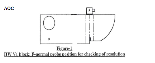
Normal (straight)beam
Transducers shall have an active an active area of not less than ½ inch2 (323mm⁰) and not more than 1 inch2 (645mm2).
The transducer shall be round or square. Transducers shall be capable of proving resolution using 3 reflections from IIW V1 Block, as shown below:
Coupling Medium
Polycell jelly, grease, water, or equivalent that shall provide satisfactory transmission of Ultrasonic sound waves.
Surface Condition
Scanning Surface shall be free of weld spatters surface irregularities or foreign materials that might interfere with the scanning during examination.
Calibration for Testing
- All calibrations and tests shall be made with the reject (Clipping or suppression) control turned off. Use of the reject (Clipping or suppression) control may alter the amplitude linearity of the instrument and invalidate test results.
- Calibration for sensitivity and horizontal sweep (distance) shall be made by the ultrasonic operator just prior to and at the location of testing of each weld.
- Recalibration shall be made after a change of operators, each 30-minute maximum time interval, or when the electrical circuitry is disturbed in any way, which includes the following :
(1) Transducer change
(2) Battery change
(3) Electrical outlet change
(4) Coaxial cable change
(5) Power outage (failure)
Reference Level
The reference level is the dB required to make peak reflection off ø 1.5mm (0.060″ ) side drilled hole SDH to 50% Full-screen Height FSH.
Indication Rating Method
The transducer shall be set in the position of IIW so that the maximum reflection from a 1.5 mm hole is received. The maximized signal shall then be adjusted to attain a horizontal reference line height indication. The maximum decibel reading shall be used as the reference level, “b” in the calculation of the indication rating.
Indication rating, d =a-b-c Where “a” – Instrument reading in decibels, when the indication from the discontinuity is adjusted to the amplitude source as the indication from 1.59mm φ hole at primary reference level. “c” – Attenuation factor is attained by subtracting 1 inch (25mm) from the sound–path distance and multiplying the remainder by ⁰. The factor shall be rounded out to the nearest dB value.
Example 1 :
Case: UT carried out on welded plates of Material Thickness 10mm, cyclically loaded structure.
- Reference dB level is set to make peak reflection off ø 1.5mm (0.060″ ) side drilled hole to 50% Full FSH.
- The reference level noted is 65 dB,
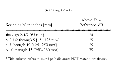
- Beam Path is 2.9”,
- Then Scanning dB is 65 + 19 dB scanning level is 84 dB, (19 dB from the below table )
- When an Indication appears on the A-scan view, the peak of the indication echo is made 50% FSH using the Gain control,
- Then record the dB level, ( in this case the indication dB level is 79dB)
- Now find the attenuation level and subtract from your dB level to find the attenuation level.
- To Find the Attenuation Level :
Attenuation = (Sound path – 1 ) x 2
Attenuation = ( 2.9 – 1 ) x 2 = 3.8, rounded off to 4.
Therefore, attenuation factor c= 4
Now we have: indication dB level a=+79dB, reference level b= +65dB, attenuation factor = 4 dB
Our reference level is 65 dB
Indication rating, d =a-b-c
d = 77- 65 – 4 = 10
Actual indication level = + 10
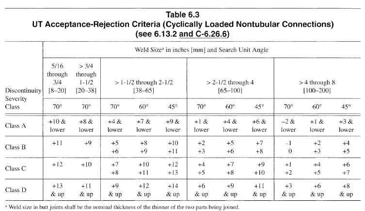
The Weld Joint, in this case, is a cyclically loaded nontubular structure, so from Table 6.3 below, + 10 and lower is found under class A rating ( ref: table 6.3) Which is rejectable regardless of length and location. Therefore in this, the Indication is rejectable.
Benefits of Acceptance Criteria in Ultrasonic Testing
Ultrasonic testing acceptance criteria help to ensure the reliability, safety, and compliance of inspected components across various industries. By establishing clear guidelines for evaluating flaws and defects detected during UT inspections, acceptance criteria offer several benefits:
Assurance of Structural Integrity:
Acceptance criteria provide a standardized framework for assessing the structural integrity of materials and components subjected to ultrasonic testing. They help ensure that critical structures, such as pressure vessels, pipelines, and welded joints, meet the required safety and performance standards outlined by regulatory bodies and industry codes such as AWS D1.1 and ASME Sec VIII Div 1.
Detection of Defects:
By defining acceptable limits for flaws and defects, acceptance criteria enable inspectors to identify and quantify anomalies detected through ultrasonic testing accurately. This helps in distinguishing between acceptable imperfections and critical defects that may compromise the integrity of the inspected components.
Prevention of Catastrophic Failures:
Implementing stringent acceptance criteria helps prevent catastrophic failures and accidents by identifying and addressing potential defects before they escalate into serious issues. This proactive approach reduces the risk of structural failures, equipment downtime, and costly repairs, thereby enhancing overall safety and reliability.
Compliance with Regulatory Standards:
Acceptance criteria ensure compliance with relevant regulatory standards and industry specifications governing ultrasonic testing practices. Adhering to established acceptance criteria, such as those outlined in ASME Sec VIII Div 1 UT acceptance criteria or ultrasonic testing standards like ASTM E213, demonstrates adherence to quality assurance protocols and regulatory requirements.
Cost Savings and Efficiency:
By accurately assessing the condition of inspected components and determining their suitability for service, acceptance criteria help optimize maintenance schedules, repair priorities, and resource allocation. This strategic approach minimizes unnecessary downtime, avoids premature replacements, and ultimately reduces operational costs.
Enhanced Confidence in Inspection Results:
Having well-defined acceptance criteria instills confidence in the accuracy and reliability of ultrasonic testing results among stakeholders, including manufacturers, inspectors, and end-users. Clear acceptance criteria facilitate transparent communication and decision-making regarding the acceptance or rejection of inspected components.
Facilitation of Continuous Improvement:
Acceptance criteria serve as a benchmark for evaluating the effectiveness of ultrasonic testing methodologies and techniques. By continuously refining and updating acceptance criteria based on feedback, advancements in technology, and lessons learned from past inspections, industries can drive continuous improvement in NDT practices and enhance overall quality assurance processes.
Implementing acceptance criteria in ultrasonic testing not only ensures regulatory compliance and safety but also promotes efficiency, cost-effectiveness, and confidence in inspection outcomes.
Continuous Improvement in Acceptance Criteria for Ultrasonic Testing
Continuous improvement in acceptance criteria for ultrasonic testing (UT) is essential to meet evolving industry needs, technological advancements, and regulatory requirements. Continuous improvement can be beneficial in the following ways:
Adaptation to Industry Changes:
The landscape of industries utilizing UT pipe testing is constantly evolving, with new materials, technologies, and inspection challenges emerging. Continuous improvement allows acceptance criteria to stay abreast of these changes, ensuring relevance and effectiveness in diverse industrial settings.
Integration of Technological Advancements:
Technological advancements in UT equipment, software, and methodologies present opportunities to enhance inspection capabilities and accuracy. Continuous improvement facilitates the integration of these advancements into acceptance criteria, enabling NDT technicians to leverage cutting-edge tools and techniques for more reliable inspections.
Compliance with Regulatory Standards:
Regulatory standards governing pipe testing, such as AWS D1.1 acceptance criteria for UT, are subject to updates and revisions to address emerging safety concerns and industry best practices. Continuous improvement ensures that acceptance criteria align with the latest regulatory requirements, promoting compliance and regulatory adherence.
Prevention of Equipment Failures:
UT pipe testing plays a crucial role in detecting flaws and defects that could lead to equipment failures or structural integrity issues. Continuous improvement ensures that acceptance criteria are robust enough to identify these potential failure points, thereby mitigating risks and safeguarding worker well-being.
Uniformity and Consistency:
Uniformity in acceptance criteria across different industries and applications promotes consistency in inspection practices, reducing variability and enhancing reliability. By striving for continuous improvement, NDT technicians can maintain uniformity in acceptance criteria, ensuring consistent levels of safety and worker protection across diverse sectors.
By embracing ongoing evaluation, feedback, and refinement, the NDT community can ensure the effectiveness of UT pipe testing methods while upholding the core objectives of safety, uniformity, and worker well-being.
Key Takeaways
- Acceptance criteria ensure that critical structures meet safety and performance standards outlined by regulatory bodies and industry codes such as AWS D1.1 and ASME Sec VIII Div 1.
- Stringent acceptance criteria help prevent catastrophic failures by identifying and addressing potential defects before they escalate into serious issues, thereby enhancing overall safety and reliability.
- Well-defined acceptance criteria optimise maintenance schedules, repair priorities, and resource allocation, minimizing downtime and reducing operational costs.
References:
1. AQC Inspection