.webp)
Table of Content
- What is Crack Depth?
- Evaluation of Concrete Cracks
- Crack Depth Measurements in Concrete
- Instruments Involved in Crack Depth Measurement
- Formula for Crack Depth Measurement in Concrete
- Formula for Crack Width Measurement in Concrete
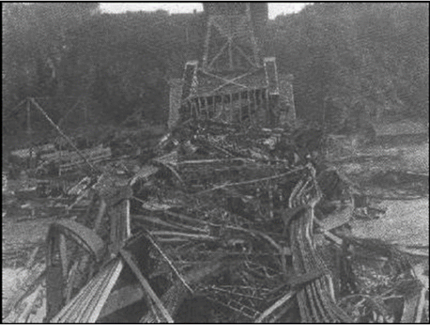
Cracks carry the same affinity towards concrete that wet cement holds towards solidifying, which can be summarised in a single word, inevitable. On 29th August 1907, The Quebec Bridge, situated in the western part of Quebec City, suffered a collapse in the southern concrete beam arm and a portion of the central section, collapsing into the St. Lawrence River situated below, causing the whole bridge to collapse in under fifteen seconds.
Concrete refers to a composite material fabricated using water, cement, and bonded together aggregates (coarse and fine) and stands as the second-most-used substance in the world only next to Water. It forms the backbone of modern industry and infrastructure, with widespread usage in reinforcing structures and being used as a layering material for myriad purposes.
Measurement of the depth of the cracks helps analyze the propagation of the fracture through the structure to determine the future action taken to curb further deterioration. Visual inspection and imagery methods discussed in the following sections help analyze the width, giving an accurate analysis of the crack if it has propagated to the foundations or the reinforced metal, depending upon the usage.
Conventional methodologies, as used during the construction of the Quebec bridge in 1907, involved the evaluation of in-situ properties of concrete that would result in damage to the concrete structure during extractions of test specimens. These specimens could not be accumulated repeatedly under this constraint, nor did it show an accurate gauge of the effects of time, loading, and Ambient factors surrounding the concrete structure. Non-destructive methods of testing are non-invasive and non-destructive techniques employed to examine the composition and integrity of materials without compromising their functionality.
What is Crack Depth?
The Crack depth refers to the dimension that indicates how deep the crack goes through the concrete structure, as indicated in the figure with the dimension h:

Methods for Crack depth measurement in concrete help calculate an important parameter to evaluate how further the crack has propagated through the concrete Added. This method helps in deciding the costs of repair, the methodology for mitigating damage, and the methodology of repairing the cracks to prevent further dilapidation. Additionally, Using an accurate concrete calculator like a Proconcretecalculator can assist in estimating material requirements for crack repairs, helping prevent unnecessary costs and ensuring precise crack restoration planning.
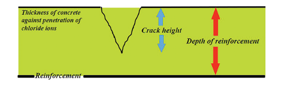
The crack depth is less; the Crack is not deep enough to reach the metal reinforcement.
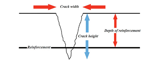
As shown in the figure, in a concrete beam, for instance, Epoxy resin can easily repair shallow cracks, depending on the usage. Still, suppose the core has been affected by the cracking. In that case, it requires a more extensive restoration as the cracks give access to the corrosive aggressors (Chloride ions) affecting the metallic assembly.
Evaluation of Concrete Cracks
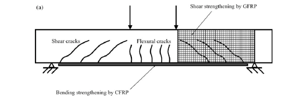
Visual Inspection, monitoring, determining the crack's properties, and determining the underlying causes of the cracking of the concrete are the initial steps in the evaluation of concrete cracks. Visual Inspection plays an important role as the angle of the crack can reflect the form of stress/load being applied to the concrete structure; for instance, shear stress in a concrete beam leads to incline cracks.
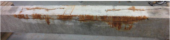
Visual Inspection can also confirm the presence of corrosive elements in the crack, which can also indicate any corrosion in the metallic assembly.
The main parameters which help us in the evaluation of the cracks are:
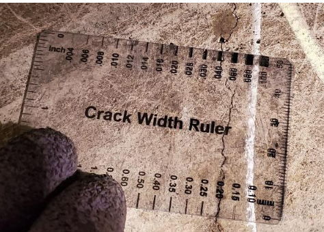
Crack Width:
This parameter helps access the severity of the cracking in concrete and helps classify them based on the evaluated severity and depending on the size. A crack width ruler is used to get a manual surface measure of the parameter.
Crack Depth:
As stated in the previous section, this parameter helps us evaluate the integrity of the concrete structure and carry out performance durability verifications. The methodology for repairs and the extent and cost can be determined using this parameter.
Crack Depth Measurements in Concrete
The methods for crack depth measurement in concrete involve several NDTs to access the crack while keeping any further deterioration from the measurement process. These methods are stated as follows:
1. Visual Examination of Concrete Cores:
One of the more popular approaches of the past decades, this method involves extracting the cores from their cracks and studying the cores and the core holes for the extent of the crack, the severity of the damage, and in turn, through physical measurements, calculating the crack depth.
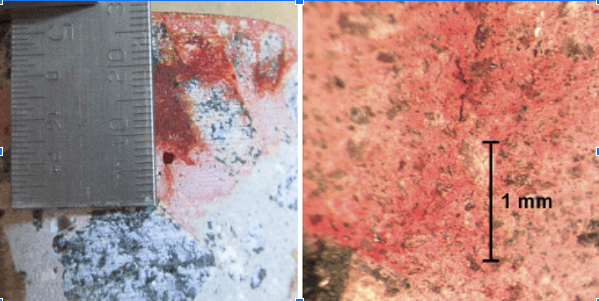
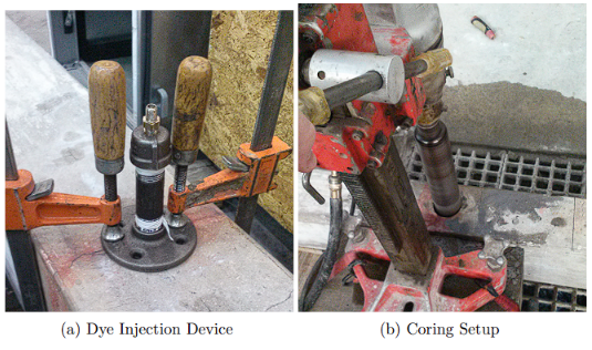
A more specialized and non-invasive approach to visual examination involves injecting the cracks with dye using minimal pressure to check any degradation of the cracks. After settling, the concrete cores will be investigated under a microscope analyzing the sample and measuring the depth of the cracks.
2. Impact-Echo Method:
The impact-echo method (IE) is stress-wave dependent, used in detecting flaws and determining the dimensions of the concrete member in various infrastructures along with specific locations of cracking, voids, and any surface delamination.
Industry guidelines on the impact-echo method are standardized as the ASTM C 1383 -04: “Standard Test Method for Measuring the P-Wave Speed and the Thickness of Concrete Plates Using the Impact-Echo Method.”
3. Ultrasonic Pulse Velocity Method (UPV):
The ultrasonic pulse velocity method is one of the oldest yet most effective NDT Methods for quality control and damage detection of concrete structures.
UPV methods have traditional usage in the quality control of welded materials, usually metals. Still, with the advent of technology, UPV has proved to be an effective method for crack depth estimation along with uniformity and quality assessment in concrete materials. Industry guidelines on UPV methods are standardized as the “Standard Test Method for Pulse Velocity through Concrete” (ASTM C 597, 2016).
Additional methods:
The Non-contact Video-based methodology is used not to obtain an absolute measure of the crack depth but to the change in the depth of the crack and stiffness of the beam, providing an accurate estimation of the progression of the deterioration and causal factors.
This methodology involves using a high-speed video camera matched with appropriate lenses, the specific target attached or labeled on the object to be measured, and a data acquisition and processing system. Owing to the high-resolution cameras and multi-threading processors available, this method helps in precise data collection to study the rate of change of crack depth and the structures.
Instruments Involved in Crack Depth Measurement
1. Visual Inspection:
Visual inspection of concrete is one of the most commonplace but underrated methods of concrete inspection. For more precise inspection, magnifying glasses may be used to thoroughly understand the cracks within the concrete structure's size, depth, and shape. Concrete cores can also be tested under a laboratory microscope for further analysis of the structure of cracks formed.
Common accessories used in this inspection method are :
- Measuring tapes, markers, and rulers
- Telescopes
- Binoculars
- Endoscopes
- Borescopes
- Fibre scopes
- Crack-width microscope and gauges
- Portable microscopes
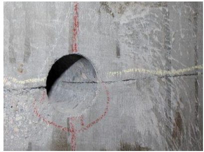
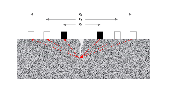
To counteract the variation in the crack area as the dye is being injected, the coring bit is positioned so that the outer edge of the core corresponds with the location where the ultrasonic equipment was placed across the width of the beam, as shown in the figure:
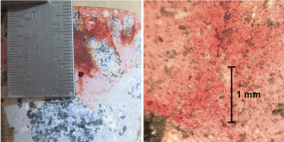
Dye injected into concrete, used for Visual Inspection of cracks
2. Impact-Echo Test:
According to the industry standardization provided by the American Society of Testing and Materials C 1383, the Impact-echo test induces stress pulses to the concrete test subject, reflected by the anomalies, cracks, and other deformities within the concrete specimen.
A highly sensitive transducer receives these resultant reflected waves. This P-wave is mathematically used to determine the properties of the cracks found within the specimen. This process is precise and gives detailed results, which provide a thorough analysis of the state of the structure being tested.
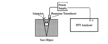
The data thus obtained in the frequency domain (owing to the Fast Fourier transform analyzer) is used further to calculate the depth of the flaw under observation. The apparatus commonly used in the impact-echo testing method includes:
> A signal processing unit that accepts incoming signals and digitizes them after processing, further sending the processed signals to the connected computer/display system.
> The number and kinds of transducers determine the instrument's configuration and may range between two to four in number. The types available are:
- Pistol transducer
- Cylindrical transducer
- WaveSpeed transducer
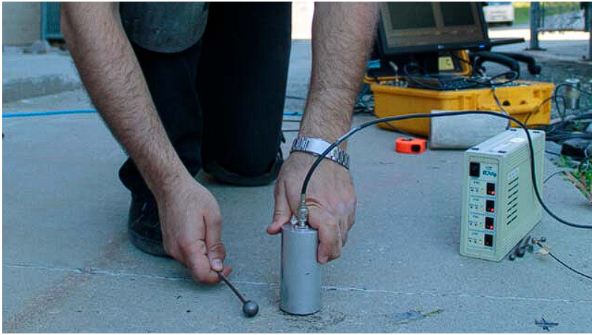
> Impactors, consisting of multiple steel balls held on spring rods, are used to create stress waves.
> Bayonet Neill-Concelman cables (Radio frequency connectors)
> Impact-Echo software
3. Ultrasonic Pulse Velocity (UPV) Test:
As per American Society of Testing Materials code C-597, Ultrasonic Pulse Velocity testing is an efficient method of crack depth analysis. Ultrasonic Pulse Velocity Testing uses transducers that transmit pulses to the concrete in direct, semi-direct, or indirect methods. The time for wave transmission is hence accounted for concerning the properties of the concrete, and an assessment of the quality of the concrete is attained.
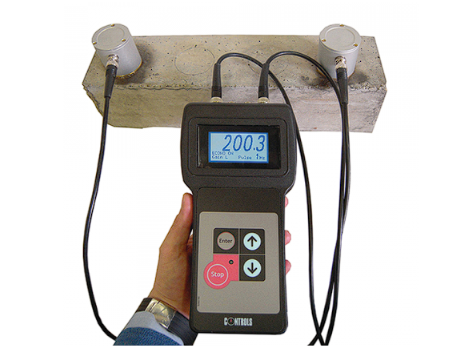
Lower transmission time accounts for better quality concrete, whereas higher travel time of the acoustic waves indicates the presence of irregularities and defects.
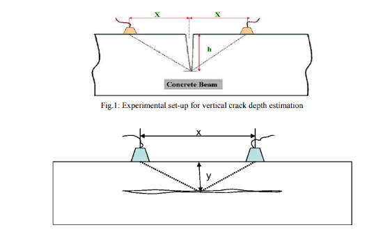
The modus operandi of the Ultrasonic Pulse Velocity test is to place transducers on both sides of the crack and carry out multiple iterations of the Ultrasonic Pulse velocity test at a varied spacing of the transducers for the calculation of the crack depth in the concrete.
Formula for Crack Depth Measurement in Concrete
Crack formation in concrete is an inevitable phenomenon. Some crack formations can be perilous, whereas others can be trivial. However, thorough monitoring, documentation, and analysis of these defects should be carried out to ensure safety. A difficulty in measuring crack depth is that the further the crack penetrates the concrete, the narrower its width gets, making it harder to determine the extent to which the crack has entered the concrete.
Different non-destructive techniques may have their formulae and methods of calculation, some of which are:
1. The formula for crack depth measurement in concrete for Ultrasonic Testing Methods:
The Ultrasonic Testing Method uses a transducer to induce impact on the surface of the concrete. Laws of refraction are hence taken into consideration, and various properties of the concrete are gauged. Crack depth is one of those measured features, the formula for which is as follows:

Where D denotes the Crack depth; Cp represents Longitudinal wave velocity; ∆t gives the time of flight of the wave; H is the distance from the crack to the receiving transducer.
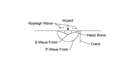
Schematics of the wave generated on the impact of ultrasonic incident waves. (Image credit: Arne, Kevin C. Crack depth measurement in reinforced concrete using ultrasonic techniques. Diss. Georgia Institute of Technology, 2014.)
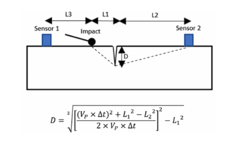
2. The formula for crack depth measurement using impact-echo methods:
The impact echo method uses the induction of a physical impact on the test surface; the resulting test waves generated comprise P-waves, S-waves, and R-waves. These waves are stress waves named Dilation waves, Distortion waves, and Rayleigh waves, respectively.
This procedure uses the Dilation waves or P-waves to measure the crack depth. The formula for this is as follows:
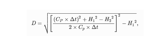
Where: D- Crack depth
Cp- Travel velocity of the P-wave
H1-Distance between the point of impact and crack
H2-Distance between the second sensor and the crack
H3-Distance between the impact point and the first sensor
∆t-Travel time of the P-wave from the impact's start to the P-wave's destination point at the second sensor.
Formula for Crack Width Measurement in Concrete
Crack defects occur within concrete structures during their service life and cause deterioration in performance ability. A thorough analysis of crack dimensions is essential, including the crack depth, width, shape, and nature. In reinforced concrete, factors like the spacing of reinforcement bars, coding of concrete, the thickness of the structure, applied load, pre-existing stresses, and physical properties of the reinforcement bars affect the size and shape of the crack, often enlarging the width of the crack defect.
As per Indian Standards for plain and reinforced concrete-456 (2000), the crack width WCR can be calculated using the following formula:

Wherein,
acr= displacement between the selected point on the surface of the concrete to the closest reinforcement bar
Cmin= minimum concrete cover over the longitudinal bar (Obtained from the section of the concrete sample)
h= overall depth of the member from the surface (Obtained from the section of the concrete sample)
X= neutral axis depth from the surface
ε= Average value of strain at the selected region
References:
1. Kevin C Arne
2. FPrimeC
3. Ndt & E International 34.2
4. Controls Group
5. NDT.NET
6. Diss. Georgia Institute of Technology
7. ASTM
8. ScienceDirect
9. JNDE
10. MDPI
11. Gambrick
12. ResearchGate


