
Table of Content
- Pipeline Isometrics
- Reading Piping Isometric Drawing
- Three Main Rules in Isometric Drawing
- How does one Identify Isometric Views?
- Key Takeaways
The inception of isometric drawings, also known as piping isometrics, marks a crucial milestone in the world of engineering. These drawings have become an indispensable tool for representing complex pipeline structures. Piping symbols and various pipeline drawings are intricately linked to isometrics, highlighting their importance in the field. Isometric drawings, often referred to as "isometrics," are a type of 3D representation that offers a unique angled view of objects.
In the context of pipeline design and engineering, Isometric Drawings have assumed a significant role. The historical absence of isometric view drawings and visualizations had significant consequences. It led to reduced clarity and understanding of complex 3D objects, increased the potential for errors, hampered efficient communication among professionals, and resulted in wasted resources. Additionally, it posed challenges in education and training. The advent of isometric drawings addressed these issues, providing a standardized and universally understood visual language, improving precision, and enhancing communication, ultimately advancing engineering and design practices.
What are Pipeline Isometrics?

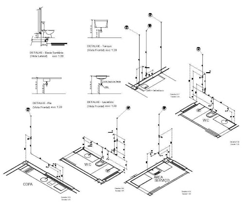
Pipeline isometrics are detailed drawings used in engineering and design to represent the 3D layout of a pipeline system on a 2D surface. Isometric drawings are commonly used in industries such as the oil and gas industry, petrochemical industry, and plumbing for planning, design, construction, and pipeline maintenance. These drawings incorporate isometric views to ensure an accurate representation of piping symbols.
Different Types of Pipeline Drawings to facilitate efficient project management and communication within the industry. Isometric drawings excel at visually portraying pipeline systems, capturing the intricate network of pipes, valves, fittings, and connections in a manner that is both understandable and standardized. These drawings employ piping symbols and conventions to depict different components of the pipeline, making it easier for engineers, designers, and other stakeholders to understand and communicate the design effectively.
Isometric Drawings are vital to the world of engineering and contribute to it in the following ways:
Clarity
Isometrics provide an unambiguous representation of pipeline structures, reducing the likelihood of misinterpretation or errors in design.
Standardization
Various types of pipeline drawings often incorporate isometric views as a standardized means of depicting complex systems, ensuring a common language for engineers worldwide.
Cost Efficiency
Isometric Drawings aid in optimizing material usage and minimizing waste, leading to cost savings in construction and maintenance.
Error Reduction
These drawings help in identifying potential issues or conflicts in the design phase, preventing costly errors during implementation.
Education
Isometrics are instrumental in training and educating future engineers, equipping them with the skills needed to work with pipeline systems effectively.
The use of isometric drawings, with their associated piping symbols and various Types of Pipeline Drawings, has revolutionized how engineers and professionals in the field approach complex designs. Their importance lies in their ability to simplify the visualization of pipeline structures, enhance communication, and ultimately contribute to the efficiency and success of engineering projects.

How to Read Piping Isometric Drawing?

While dealing with complex pipeline systems, the operators' aptitude for reading isometric pipeline drawings is imperative. Isometric drawings provide a three-dimensional representation of pipng systems on a two-dimensional plane, offering valuable information for engineers, designers, and other stakeholders. The 30-degree angle ensures that all three axes (length, width, and height) are equally foreshortened, providing a balanced perspective.
1. Piping Symbols:
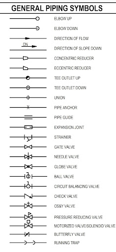
- Pipes:

In isometric drawings, pipes are represented as lines. The thickness and style of the lines may vary to indicate different pipe materials, sizes, or attributes.
- Fittings:

Fittings are used to connect and redirect pipes. Common fittings include elbows, tees, reducers, and couplings. Each type of fitting is represented by a specific symbol. Fittings, such as elbows, tees, reducers, and couplings, have distinctive symbols. For instance, a 90-degree elbow is represented as a quarter-circle.
- Valves:
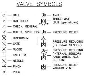 Valves control the flow of fluids in a pipeline. Different valve types, such as gate valves, globe valves, and ball valves, are depicted using distinct symbols.
- Flanges:

Flanges are used to connect pipes and other components. They are represented by a circle with bolt holes.
- Strainers and Filters:

Symbols for strainers and filters are used to denote their position within the system.
- Instruments and Sensors:
Instruments like pressure gauges, flow meters, and sensors have their unique symbols on Piping Drawings, making it clear where they are installed in the system.
2. Piping Layout:

- Pipe Routes:
Lines indicate the direction of the pipeline. Different styles or colors may be used to distinguish between process lines, utility lines, or different services.
- Elevations:
Elevations on the drawing can help determine the height or depth of pipes, which is crucial for installation.
- Branches and Connections:
Where pipes intersect, symbols indicate the type of connection, such as a weld, flange, or threaded connection.
- Isometric Scale:
Isometric drawings often incorporate a scale that ensures accuracy in measurements and scaling within the drawing.
Annotation and Labels:
- Pipe Sizes:
Labels specify the sizes of pipes, usually indicating both the nominal diameter and the schedule (e.g., 4" SCH 40).
- Flow Direction:
Arrows are often used to indicate the flow direction of fluids within the pipes. These arrows can show whether the flow is in one direction or bi-directional.
- Connection Points:
Dots or small circles at the ends of lines represent connection points. For instance, a dot at the end of a line could indicate the location where a pipe is connected to a valve.
- Component Identification:
Each component, including fittings, valves, and instruments, is labeled with an identifier or tag that corresponds to a legend.
- Notes and Dimensions:
Additional notes and dimensions may be included to provide crucial information regarding materials, specifications, and clearances.
3. Color Codes:
Color codes are sometimes used in isometric drawings to distinguish between different types of lines, components, or services. These codes can enhance clarity and organization.
- Legends and Keys:
A legend or key is typically included within the drawing or in a separate document, explaining the symbols and labels used in the isometric drawing. This key is essential for understanding the drawing's components and their functions.
- Isometric Scale:
Isometric drawings may employ a scale where each unit of measurement along one axis corresponds to the same distance in all three dimensions. This is crucial for accurate measurement and scaling within the drawing.
Three Main Rules in Isometric Drawing
Creating accurate and consistent representations of three-dimensional objects requires adherence to certain rules. The rules of reading and drawing isometric drawings include:
1. Parallel Lines:
Isometric Drawings require that lines parallel to the three primary axes (X, Y, and Z) remain parallel, with horizontal lines at a 30-degree angle to the horizontal axis (X), vertical lines remaining truly vertical, and lines along the depth (Z) axis at a 30-degree angle in the opposite direction of the horizontal lines.
2. Uniformly compressed:
Isometric drawings follow the principle of equal compression. This ensures that all dimensions—length, width, and height—are proportionately shortened, preserving balanced proportions, and preventing distortion.
3. Isometric Scale:
An isometric scale is often used in Isometric Drawings, where consistent units of measurement exist along all three axes, which aids in precise measurement and maintaining accurate relationships between components.
Explore how to enhance your designs - check out our article on Pipeline Isometric Drawing Softwares!
How does one Identify Isometric Views?

Isometric views involve considering axis orientation, equal foreshortening, the use of an isometric scale, visual appearance, Isometric Symbols, and practice. This skill is valuable in engineering, design, and technical illustration, allowing for a clear representation of three-dimensional objects on a two-dimensional surface. The factors to be kept in mind while trying to identify isometric views include:
- Axis Orientation:
Isometric drawings have three primary axes—X, Y, and Z. Horizontal lines are typically at a 30-degree angle to the X-axis, while vertical lines remain truly vertical. The lines on different axes are also at 30 ⁰ angles but in different directions.
- Uniform Compression:
Isometric drawings adhere to equal dimensioning, meaning all dimensions—length, width, and height—are proportionately shortened, maintaining consistent proportions.
- Isometric Scale:
An isometric scale is often used in these drawings. It ensures that each unit of measurement along one axis corresponds to the same distance in all three dimensions, allowing for accurate measurement and scaling.
- Visual Effect:
Isometric views should have a balanced, 3D-like appearance without vanishing points or extreme distortions. Objects appear as if viewed from an angle but don't recede into the distance as they would in true perspective drawings.
- Symbols and Conventions:
Getting acquainted with symbols and conventions used in isometric drawings can aid in identification.
- Experience:
Sufficient practice and experience improve an individual's skill in recognizing isometric views. If you want to learn how to construct an isometric view of an object, check out this easy-to-understand video.
Key Takeaways
- Reading isometric drawings is a vital skill, particularly for professionals in engineering and design, as isometric drawings provide a 3D-like perspective on a 2D plane.
- Efficiently interpreting isometric drawings involves understanding essential characteristics like parallel lines, equal foreshortening, and using an isometric scale, along with consistent practice for improved recognition of isometric views.
References:
1. Machinery Spaces
2. Aveva
3. Pipe Flow Software
4. Vector Stock
5. All About Piping
6. Timken Power Systems
7. IndiaMart
8. ScienceDirect


