Introduction
Ensuring reliable ultrasonic inspection of aerospace-grade metals remains a core challenge in evaluating safety-critical components. Key challenges include accommodating surface tolerances and complex geometries, preserving or improving near-surface resolution, and increasing signal-to-noise ratio (SNR). Materials like Ti-6Al-4V (Ti64) are particularly challenging due to their high ultrasonic backscatter, which can obscure real flaws or produce false indications. Immersion-based phased array inspections are widely used for billets, forgings, and plates. In these applications, the goal is to reliably detect indications that exceed predefined thresholds, typically based on amplitude (e.g., 80% full screen height, FSH) and SNR (e.g. greater than 2.5) as specified in standards such as AMS2628. Meeting these criteria is critical for compliance with acceptance requirements for high-reliability components, such as those used in jet engines. Meanwhile, manufacturers must also maintain high production throughput, making inspection speed a key consideration. Recent advances in phased array instrumentation, high-bandwidth data transmission, GPU-accelerated computing, and sophisticated ultrasound imaging algorithms now enable significantly faster inspections without compromising sensitivity or resolution.
Limitations of Current Techniques
Traditional ultrasonic testing typically relies on a single-element transducer that is mechanically scanned across the part, often using immersion tank systems to ensure consistent coupling. In this approach, the focal distance and beam spot size are determined by the physical characteristics of the probe, such as its diameter and the mechanical lens, often requiring the use of multiple probes or repeated scans to inspect different depths. Although conventional systems can employ a surface-following gate to track the front-wall echo and adjust the time window for flaw detection, this technique does not correct for focus degradation caused by geometric or surface tolerance deviations in the part. As a result, inspections can be susceptible to false rejections or acceptances, especially in coarse-grained materials like titanium alloys (e.g. Ti64). In addition, the overall process tends to be slower due to the need for mechanical scanning in a tight scan resolution. Additionally, since beamforming is hardwired into the system, there is little opportunity for post-processing flexibility or advanced data analysis.
Phased Array & Surface Adaptive Techniques
Phased Array probes provide the ability to electronically control focusing and allow you to focus the beam at several depths without the need for multiple probes like in conventional UT based inspections.
Surface Adaptive Total Focusing Method (ATFM) and Surface Adaptive Plane Wave Imaging (APWI) represent an even more significant advancement over conventional phased array techniques by eliminating the reliance on predefined focal laws based on idealized, flat geometries. In practice, even components labeled as flat often exhibit surface variations of several millimeters due to manufacturing tolerances. Instead of assuming a perfect surface, ATFM and APWI reconstruct the true surface profile directly from Full Matrix Capture (FMC) or Plane Wave Imaging (PWI).
This method is highly tolerant of geometric variations, including changes in water path in some cases of more than 10 millimeters, which would typically distort the focusing quality in traditional systems, thus possibly missing a real flaw detection. In standard phased array inspections, even small deviations in part flatness or water path can significantly impact focusing if not accounted for in advance. ATFM and APWI avoids this problem by adjusting the focusing during image reconstruction, using the same dataset. This eliminates the need for separate scans to first characterize the surface and then re-scan with adjusted focal laws, allowing both surface adaptation and flaw detection to be completed in a single acquisition.
Why choose APWI over ATFM?
While Adaptive Total Focusing Method (ATFM) is often considered the gold standard for resolution, this performance comes at the cost of increased computation time, larger data files, and consequently longer overall inspection durations. Adaptive Plane Wave Imaging (APWI), by contrast, offers significantly faster inspection speeds, albeit sometimes with a modest trade-off in resolution. However, depending on the material properties, APWI can achieve resolutions equal to, or in some cases even better than, ATFM.
This is particularly true for attenuative materials or those with high ultrasonic grain scattering, where APWI’s broad energy distribution from its plane wave pulsing pattern provides superior penetration and signal quality. Thus, achieving higher SNR and resolution without sacrificing inspection speed. Moreover, APWI is often faster not just compared to ATFM, but even relative to conventional phased array (PAUT) techniques. For example, consider a linear scan using a 32-element aperture across a 128-element array. Traditional PAUT would require 97 shots, whereas APWI could achieve the same coverage with as few as 11 shots. Furthermore, if you apply zone focusing and dynamic depth focusing (DDF) this would increase the number of shots even more. While APWI does involve additional computation, the overall inspection time including data acquisition and reconstruction can still be significantly reduced. Major improvements in computing technology such as GPU parallel processing make APWI an attractive option for high-throughput applications such as immersion plate scanning, billet inspection or forging inspections for aerospace.
Figure 1 is a comparison of PWI and APWI in an immersion scenario where the water path is identical to the appropriate pre-defined value. There are two plates welded together with some detected lack of fusion flaws. You can see the imaging of the weld defects in this case are similar. However, the next two following figures will show the limitations when an adaptive algorithm is not used to provide this correction.
Figure 1: PWI and APWI at Optimal Water Path
In Figure 2, the water path was intentionally shortened by 5mm for both PWI and APWI. Consequently, the weld defect appears distorted when using standard PWI due to the incorrect water path. However, APWI is able to correct the focal laws in real time, producing a clearer image despite the suboptimal physical setup. In addition, the true depth of the weld flaw is maintained appropriately in APWI whereas in PWI the weld flaw depth is corrupted and shows up earlier in distance.
Figure 2: The water path is too short
In Figure 3, you can see how the APWI algorithm adjusts the focusing to compensate when the water path becomes too long. In the case of PWI, the water path was lengthened by 4mm and for APWI it was lengthened by 16mm. Even though the water path in APWI was increased by 4 times the distance of PWI the image remains well focused. Neither conventional single-element ultrasound nor standard phased array techniques are capable of this level of adaptive correction. By applying real-time surface adaptive focusing, APWI maintains inspection reliability even in the presence of surface tolerance variations or setup inconsistencies.
Figure 3: Water path is too long
Why does data rate matter?
As advanced imaging techniques like FMC, TFM, and APWI demand significantly more data, it becomes critical to improve both data transfer speeds between the instrument and the PC.
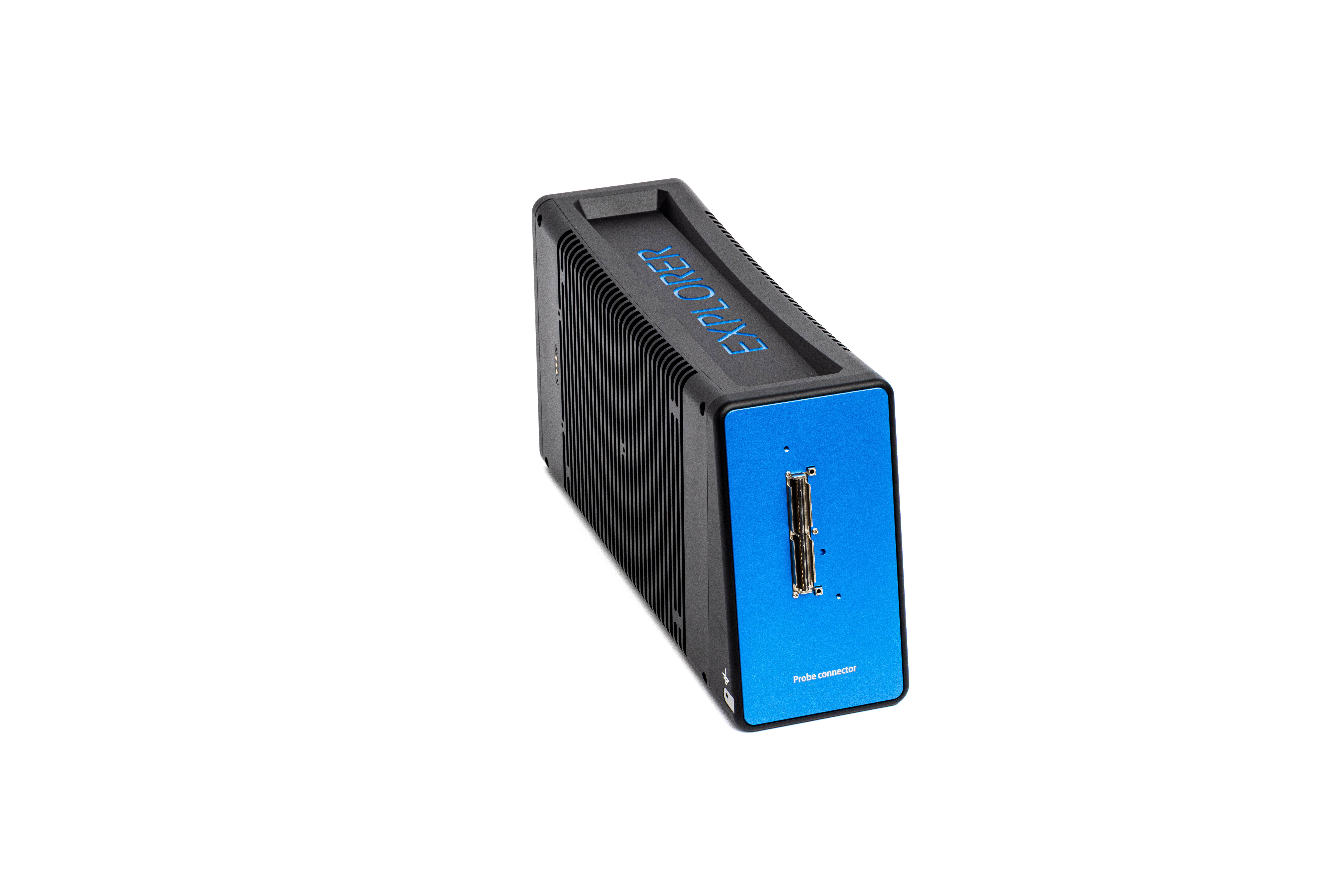
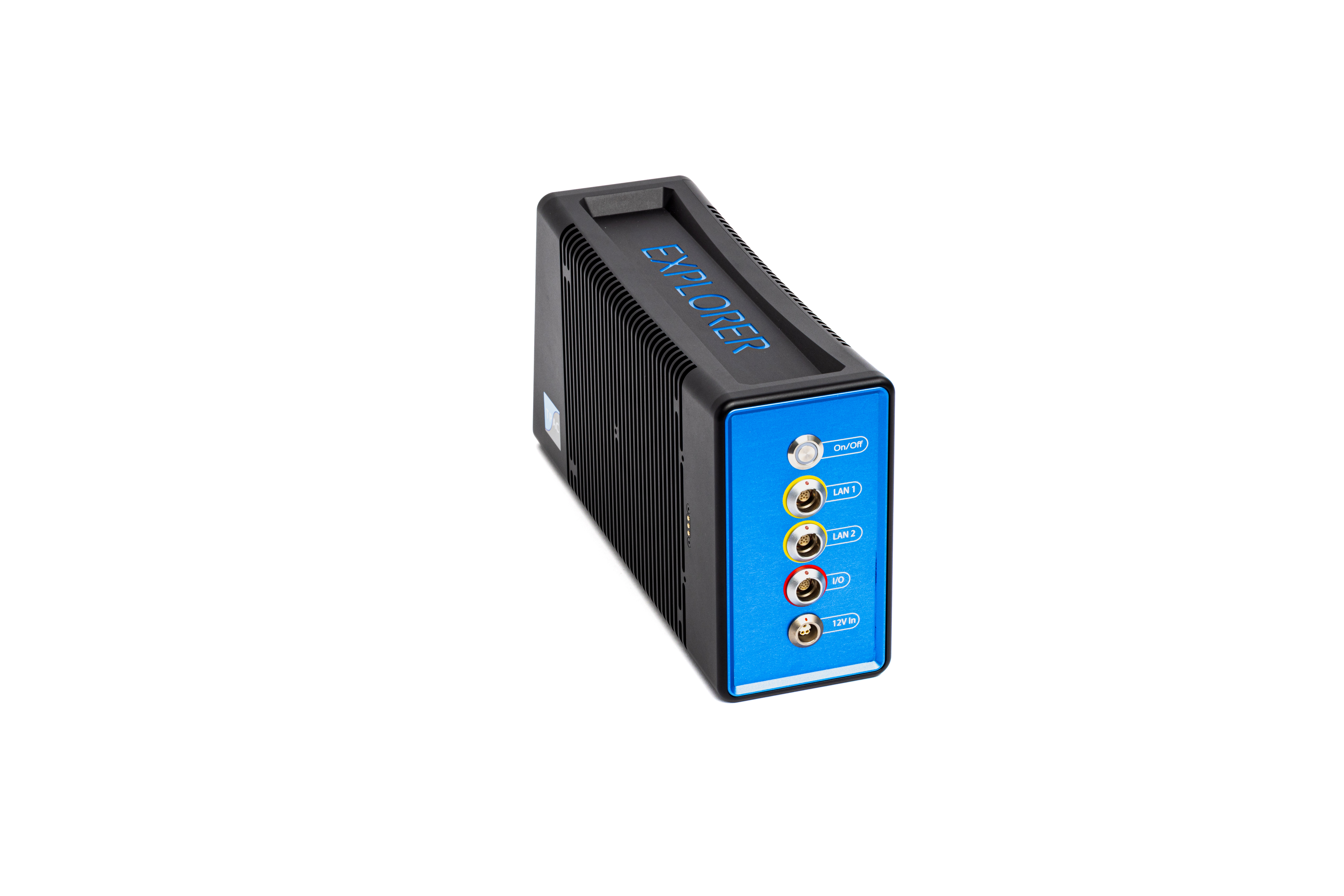
TPAC’s Explorer MAX 128/128 addresses these challenges. It is a compact, rugged, and high-speed phased array instrument designed for precision applications. With a data transfer rate of 2 GB/s enabled by 10G Ethernet architecture, it ensures rapid communication between the instrument and processing system. Unlike many other phased array systems capable of Full Matrix Capture, which tend to be large and difficult to integrate, the Explorer MAX offers a small form factor ideal for embedded or robotic applications.
This compact design also enables practical placement of the instrument closer to the probe, which helps minimize signal loss by allowing the use of shorter probe cables. In traditional setups, this proximity is often not feasible due to the bulk of the equipment. The Explorer MAX overcomes that barrier, making high-performance imaging more flexible and deployable in industrial environments.


Conclusion
As aerospace manufacturers continue to demand more reliable inspection techniques, the need for advanced ultrasound imaging technologies becomes increasingly critical. TPAC’s integration of Surface Adaptive Plane Wave Imaging (APWI) and other advanced imaging algorithms such as Phase Coherence Imaging (PCI), coupled with high-speed, compact instrumentation like the Explorer MAX 128/128, directly addresses the key limitations of traditional ultrasonic methods. These technologies not only accommodate surface variation and material challenges, such as the high backscatter of titanium alloy, but also enable high-throughput inspections without sacrificing inspection detectability. By leveraging fast data transfer via 10G Ethernet and real-time GPU processing, TPAC delivers practical solutions. Whether inspecting billets, plates, or forged components, these innovations support the aerospace industry's ongoing pursuit of flight safety with better inspection performance.
Author: TPAC (The Phased Array Company)


