
Table of Content
- Introduction
- The short answer
- How each technique works
- Scan image examples
- Decision table
- Comparison by factor
- How to choose
- Frequently asked questions
Introduction
Every inspection manager will eventually be asked the same question. Should we stick with traditional UT, advance to phased array, or pursue TFM? There isn't really a single correct answer to the conventional vs advanced ultrasonic testing debate. Each technique wins on different jobs. What you're looking for, where it's likely to be, what the part is made of, what the code will accept, and how much time and money the task can afford will all determine which one wins. This guide takes these one at a time.
The short answer
As long as the code is satisfied with manual inspection and no stored image is required, conventional UT still pays its way on thickness readings, spot inspections, and basic welds.
The mainstay of encoded weld inspection is PAUT. It's typically where you end up if you require a permanent record, quicker coverage, or a code-accepted substitute for radiography.
In situations where characterization is crucial, such as small or oddly angled planar flaws, early-stage damage, and complicated geometry where PAUT's fixed focal laws may leave soft spots in resolution, TFM deserves its place.
How each technique works
Conventional UT
This is the technique most technicians learned. One beam is sent into the component at a single, fixed angle using a single- or dual-element probe. The operator manually moves the probe, often in a raster pattern, until the weld is covered while keeping an eye on the A-scan, which graphs amplitude versus time. Do you want a different angle? Change the wedge or the probe. Additionally, nothing is saved unless the scan is encoded. Whatever the operator writes down is the record.
Phased array UT (PAUT)
There are many small elements in a single housing when you open a phased array probe; in normal weld probes, there are between 16 and 64. Each collection of precisely timed delays used by the instrument to fire them is referred to as a focal law. By altering the focal laws, the same probe can focus wherever you desire, slide one angle along the array (a linear scan, or E-scan), or sweep through a range of angles (a sectorial scan, or S-scan). When an encoder is applied, the entire data set is recorded and prepared for further analysis, auditing, or comparison with the next inspection.
Total focusing method (TFM)
Full matrix capture (FMC) is typically the first step in TFM. You get an A-scan for each transmitter-receiver pair because each element fires in turn while every element listens. Then, rather than focusing at the few depths PAUT utilizes, the instrument focuses synthetically at every point in the image zone. You get flaw tips and shapes that are typically easier to read, as well as resolution that is consistent throughout the entire zone. The instrument must support FMC/TFM, but it runs on the same array probes as PAUT. Some systems use plane wave imaging (PWI) instead of FMC to collect data faster.
Since TFM runs on the same array probes as PAUT, the phased array fundamentals carry over to both. For a deeper look at focal laws, E-scans and S-scans, see our detailed guide to phased array ultrasonic testing.
→ Read: What Is Phased Array Ultrasonic Testing?
Scan image examples
Pictures help here. Below is one flaw, a sidewall lack of fusion in a single-V butt weld, as each technique would typically show it. It's a simplified schematic drawn for comparison, not real instrument data.
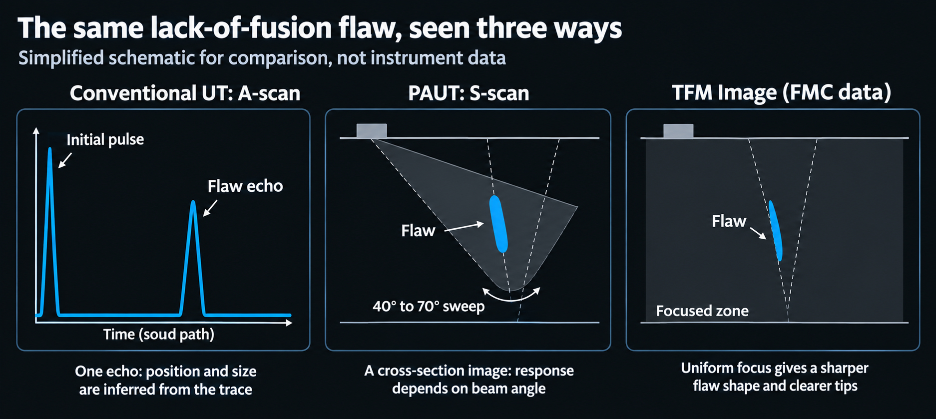
Conventional UT (A-scan). One echo on the trace. That's all. The operator determines the location of the flaw based on the sound path, beam angle, and probe position. Size is determined by either sliding the probe until the signal diminishes or by measuring the amplitude. You have to rely on the operator's expertise and whatever is included in the report because you never get a visual of the weld.
PAUT (S-scan). The weld is finally visible at this point. The flaw lights up along the fusion face when a fan of angles sweeps over the cross-section from a single probe position. One thing to be aware of is that the reflection of a planar flaw varies depending on the angle. At one angle, it may appear large and bright, and at another, it may appear small or faint. Typically, the encoded image is used to determine the length and height.
TFM. The flaw seems sharper and its tips are simpler to locate since everything in the zone is in focus. When you use a skip mode like TT-T, which causes the sound to bounce off the back wall first, you can frequently image the flaw considerably more accurately in terms of its actual form and angle. It is also much easier to distinguish geometry from a true flaw because the root and cap are more clearly seen.
No two configurations produce exactly the same image. What you see is altered by the probe, wedge, frequency, material, and setup. Therefore, ask your inspection provider for scans from their qualified procedure before approving a technique, preferably on a joint similar to yours.
Decision table
Use this as a first pass, not the final word. "Yes" means the technique is a sound choice for that factor under typical conditions; "No" means another technique usually does it better, or the technique isn't designed for it. In the end, the procedure, the qualified people you can get and the governing code make the call.
Factor | Conventional UT (manual) | PAUT | TFM |
|---|---|---|---|
Covers planar flaws (cracks, lack of fusion) at several angles from one probe position? | No | Yes | Yes |
Detects volumetric flaws (porosity, slag)? | Yes | Yes | Yes |
Best option for characterizing flaws and locating tips? | No | No | Yes |
Strongest option for early-stage damage, such as HTHA? | No | No | Yes |
Best choice for quick spot thickness readings? | Yes | No | No |
Most efficient for mapping corrosion over large areas? | No | Yes | No |
Suitable for simple plate and pipe butt welds? | Yes | Yes | Yes |
Well suited to complex geometry (nozzles, branches, tapers)? | No | Yes | Yes |
Usable on coarse-grained or austenitic material with a dedicated procedure? | Yes | Yes | Yes |
Covered by ASME Section V and ISO standards? | Yes | Yes | Yes |
Widely referenced by construction codes and client specifications? | Yes | Yes | No |
Commonly used in place of radiography under ASME Code Case 2235? | No | Yes | No |
Lowest equipment cost? | Yes | No | No |
Needs technique-specific advanced training? | No | Yes | Yes |
Fastest for full encoded weld coverage? | No | Yes | No |
Shows an image of the weld cross-section? | No | Yes | Yes |
Leaves a permanent, auditable record? | No | Yes | Yes |
Comparison by factor
Defect type
Any of the three will find planar and volumetric flaws, as long as the beam reaches them at a sensible angle. The real differences are in coverage and in how well you can tell what you've found.
The most important flaws for integrity are planar ones, including cracks and lack of fusion, which are also the most sensitive to beam angle. You can only locate them consistently with traditional UT if the operator covers the entire volume and selects the proper angles. Many of those risks are reduced with PAUT, where a single probe sweeps a variety of angles and the encoded image indicates precisely where coverage begins and ends. TFM delves deeper into characterization. Better height sizing results from sharper tips, and skip modes can more clearly display the shape and orientation of a flaw.
The fastest method for taking spot readings for wall loss is still to use a traditional thickness gauge. However, encoded PAUT linear scans will create a C-scan thickness map much more quickly than anyone using a manual grid if you need to map a large area.
TFM's additional resolution truly pays off in early-stage damage. For example, since its 2020 update, API RP 941 has included TOFD, PAUT, and FMC/TFM among its recommended ultrasonic techniques for high-temperature hydrogen attack (HTHA).
Geometry
On simple plate and pipe butt welds, all three are adequate, and standard UT is frequently sufficient if the code permits it. Another issue is complex geometry. Manual scanning is slow and challenging to verify since nozzles, branch connections, tapers, and thickness transitions require numerous angles and probe locations. PAUT handles complex geometry with planned focal laws and encoded scans. When a flaw could be present at nearly any depth or angle, TFM helps by keeping the entire zone in focus. Either model the scan plan or test it on a representative mock-up before moving on.
Material
Fine-grained carbon and low-alloy steels are ideal for all three techniques. Anisotropic and coarse-grained materials are not. The beam can be scattered and skewed off course by austenitic welds, dissimilar metal welds, and certain castings. Low-frequency, dual-element longitudinal-wave probes suffice for conventional UT. Longitudinal waves can be focused and steered using PAUT's dual linear and dual matrix arrays. TFM can sharpen the image, but it depends on precise velocity and geometry models, so anisotropy can distort the image unless the setup accounts for it. Regardless of the method you choose, these materials will require a dedicated, demonstrated procedure.
Code acceptance
Quite often, the code makes the decision before technical merit even gets a look-in.
- Conventional UT is covered by ASME Section V Article 4, AWS D1.1 and ISO 17640 with ISO 11666, and it's still widely accepted for manual welding examination. The catch: manual conventional UT can't replace radiography where the code calls for computer-based data acquisition.
- PAUT is covered by ASME Section V Article 4 (Mandatory Appendices IV and V), by ISO 13588 with acceptance levels in ISO 19285 and, since the 2020 edition, by Annex H of AWS D1.1. ASME Code Case 2235 lets you use ultrasonic examination in lieu of radiography on Section I and Section VIII vessels when its conditions are met, and one of those conditions is automatic computer-based data acquisition. In practice, that usually means encoded PAUT, TOFD or both.
- TFM is covered by ASME Section V Article 4, Mandatory Appendix XI (added in the 2019 edition), and by ISO 23864 for welds and ISO 23865 for general use. Fewer construction codes and client specifications mention it so far, so check that both the code and the client will accept it, and plan to qualify the procedure on representative samples.
Cost
The cost of equipment increases from traditional UT to PAUT to TFM. The least expensive kit consists of a set of probes and a conventional flaw detector. Array probes, wedges, encoders, scanners, and analysis software are all added by PAUT. TFM makes use of many of the same probes, but it requires an FMC/TFM-capable device and typically additional storage and processing power.
Personnel costs follow the same pattern. Conventional UT technicians are the easiest to find. Technique-specific training and expertise are required for PAUT and TFM, and it is most difficult to find skilled TFM technicians.
However, the picture can change when you include the cost per weld. Because coverage is quicker, reports are generated directly from the data, and, unlike radiography, there is no exclusion zone preventing other trades from operating nearby, encoded PAUT frequently results in lower costs on high-volume work. Price the whole job, not the day rate.
Speed
Conventional UT is fast for spot checks but sluggish for full weld coverage because each angle must be rastered by hand. Since one or two line scans along the weld can cover the volume at several angles in one go, PAUT is typically the fastest method for encoded weld inspection. Compared to PAUT, TFM typically gathers and processes more data. The number of elements, the size of the image zone, and the fine grid required to achieve amplitude fidelity limits—such as the 2 dB limit in ASME Section V, Appendix XI—all affect how quickly it operates. For this reason, rather than performing TFM along every meter of weld, many teams utilize it selectively to characterize indications PAUT has already detected or to examine crucial sections.
Code acceptance is the first question in the selection steps below, and it often settles the choice before technical merit does. For a fuller picture of which codes govern ultrasonic examination, see our detailed guide to ultrasonic testing standards and codes.
→ Read: Ultrasonic Testing Standards and Codes
How to choose
When you're stuck, go through the following five questions in order. They will typically steer you in the right direction:
What will the code and the client specification accept?
When it is time to replace radiography or to keep a permanent record, conventional (manual) UT is typically not a contender.
What do you need to catch?
Spot wall loss points to thickness gauging, general weld flaws to PAUT, and small, early-stage or hard-to-characterize damage to TFM.
What is the difficulty of the geometry and materials?
Any of the three can be used for simple, fine-grained welds. Complex geometry or coarse-grained material tips the balance toward PAUT or TFM with a demonstrated procedure.
What type of record do you require?
Go encoded if anyone will audit the data, or if you'll be looking for a comparison at the next outage.
How much will the entire job cost?
Add up equipment, staff, coverage speed, reporting and any production downtime, not just the day rate.
There are lots of programs that eventually find themselves using all three: conventional UT for thickness readings and spot checks, PAUT for day-to-day weld examination and corrosion mapping, and TFM for indication characterization and/or investigations into critical and complex areas.
Frequently asked questions
PAUT vs UT: is PAUT always better?
No. PAUT covers a full weld faster and leaves a permanent record, but for spot thickness readings, simple checks or small jobs, conventional UT is often quicker to set up and cheaper to run.
Will TFM replace PAUT?
Not for most work today. TFM resolves and characterizes flaws better, but it produces more data, usually runs slower and is mentioned in fewer construction codes. It tends to come in where the extra resolution would actually change the decision.
Can PAUT replace radiography?
Often, yes. Through Code Case 2235, ASME Section I and Section VIII allow encoded ultrasonic examination in lieu of radiography when the case's conditions are met, including a qualified procedure, qualified personnel and specified acceptance criteria. Always check what the governing code actually permits.

There are no comments yet!