Table Of Contents
- Introduction
- Understanding Ultrasonic Testing
- Why UT is a Game-Changer
- Wave Modes and Sound Behaviour in the Material
- Core Methods of Conventional UT
- The Ultrasonic Examination Procedure
- Applications of Ultrasonic Testing
- Advantages of Ultrasonic Testing
- Limitations of Ultrasonic Testing
- Best Practices for Effective UT
- Emerging Trends in Ultrasonic Testing
- Conclusion
- FAQ
Introduction
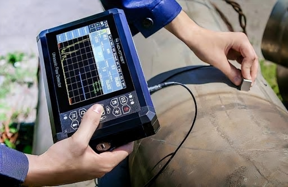
Ultrasonic testing (UT) is one of the most widely used volumetric methods in industrial NDT, and for most inspectors it is the method they reach for first when the question is what lies inside a component rather than on its surface. A weld on a pressure vessel, remaining wall thickness in a corroded line, a suspected inclusion in a forging — all of these are answered with a transducer, a couplant film and an A-scan.
This article covers conventional UT as it is actually applied: how sound behaves in the material, the core techniques, the sequence of a controlled inspection, where the method performs well, and where it does not. It is written for technicians and engineers who already work in NDT and need the fundamentals set out accurately rather than introduced from scratch.
It covers:
- How sound propagates in a material, and the wave modes UT relies on
- The core methods — pulse-echo, through-transmission and resonance
- A step-by-step look at the ultrasonic testing procedure
- Applications across welding, corrosion monitoring, aerospace and power generation
- The advantages and limitations that determine when UT is the right choice
- Best practices, and where the method is heading
Understanding Ultrasonic Testing
At its heart, ultrasonic testing uses high-frequency sound waves—typically 0.5 to 15 MHz—to probe materials for internal defects or measure properties like thickness. The principle of ultrasonic testing is straightforward: sound waves travel through a material until they hit a boundary, like a crack or the back wall, and reflect back. By analyzing these reflections, technicians can detect, locate, and characterize flaws with remarkable precision. It's like echolocation for industrial components, revealing what's hidden beneath the surface without a single cut.
UT stands out among ultrasonic NDT techniques because it's non-invasive, highly sensitive, and versatile. It can spot tiny cracks, voids, or inclusions that could spell disaster in high-stakes industries like aerospace or oil and gas. Plus, it requires minimal preparation compared to destructive methods, saving time and costs while ensuring safety.
Why UT is a Game-Changer
For NDT professionals, UT's ability to detect subsurface flaws—voids, inclusions and lack of fusion deep inside a component—sets it apart from surface methods like liquid penetrant or magnetic particle testing, which reveal only what breaks the surface. The trade-off runs the other way for surface-breaking defects, where PT and MT are usually the better choice, because conventional UT has a dead zone immediately beneath the surface. UT is also portable, safe (no radiation risks), and delivers real-time results, making it ideal for both shop and field inspections. Whether you're ensuring a weld's integrity or measuring pipe wall thickness, UT provides the data needed to make informed decisions.
Wave Modes and Sound Behaviour in the Material
Everything downstream in a UT inspection — probe selection, refracted angle, calibration, sizing — follows from how sound behaves once it enters the component. Three properties matter most.
Acoustic Impedance and Why Couplant Is Necessary
Acoustic impedance is the product of a material's density and its sound velocity. When a sound wave meets a boundary between two materials, the proportion of energy reflected depends on the difference in impedance across that boundary.
The mismatch between air and steel is extreme, and almost all the energy is reflected at an air gap. This is why a probe placed dry on a surface transmits effectively nothing into the part, and why couplant is not a convenience but a requirement: it displaces the air film and provides an intermediate impedance path so that useful energy crosses into the component. It is also the reason UT detects planar flaws so well — a crack or lack of fusion presents an internal air interface and reflects strongly.
The Three Wave Modes Used in Conventional UT
Longitudinal (compression) waves. Particle motion is parallel to the direction of travel. These are the fastest waves in a given material and are what a straight-beam (0°) probe generates. Longitudinal waves are used for thickness measurement, lamination checks in plate, and volumetric inspection of forgings and castings. In steel they travel at roughly 5,900 m/s.
Shear (transverse) waves. Particle motion is perpendicular to the direction of travel. Shear waves travel at roughly half the longitudinal velocity — about 3,230 m/s in steel — which gives a shorter wavelength at the same frequency and therefore better resolution for small defects. Shear waves are the working mode for angle-beam weld inspection. They do not propagate in liquids or gases, since those media have no shear stiffness.
Surface (Rayleigh) waves. These travel along the surface to a depth of roughly one wavelength, at approximately 90% of the shear velocity. They are used for detecting surface and near-surface cracks on components where access or geometry rules out other approaches.
Refraction, Mode Conversion and the Angle-Beam Probe
When sound crosses a boundary at an angle, it refracts according to Snell's law, and the sine of the angle in each medium is proportional to the velocity in that medium. Because longitudinal and shear waves travel at different velocities, they refract at different angles — so a single incident beam splits into two refracted beams inside the component. This splitting is mode conversion.
This behaviour is what makes angle-beam inspection possible. As the incident angle in the wedge increases, the refracted longitudinal wave reaches 90° and disappears from the material at the first critical angle. Beyond that point only the shear wave remains, giving a single clean beam with no competing longitudinal signal to confuse interpretation. Push further and the shear wave also reaches 90° at the second critical angle, beyond which a surface wave is generated instead.
Angle-beam probes are therefore built with wedge angles that place the refracted shear beam between these two limits, which is why standard probes are supplied at 45°, 60° and 70°. The choice depends on weld geometry and the orientation of the expected flaw: the aim is to strike the fusion face as close to perpendicular as possible, since a planar defect reflects most strongly when the beam meets it square on. A well-oriented 45° beam will find a lack of sidewall fusion that a poorly chosen 70° beam passes straight by.
Mode conversion also occurs at internal reflectors and at the back wall, which is a common source of spurious indications. Distinguishing a genuine flaw from a mode-converted signal or a geometric echo is a large part of what separates a competent interpreter from a trained one.
Attenuation, Beam Spread and the Near Field
Sound loses energy as it travels, through absorption and through scattering at grain boundaries. Attenuation rises with frequency and with grain size, which is why coarse-grained materials such as austenitic stainless steel and cast iron are difficult to inspect and why thick sections are examined at lower frequencies.
The beam itself is not a straight column. Close to the probe, in the near field, interference between wavefronts produces a chaotic pressure distribution in which amplitude cannot be reliably related to reflector size. Beyond the near field the beam diverges at a predictable angle and amplitude falls off in a regular way. Sizing based on amplitude is only valid in the far field, and near-field length is one of the factors governing probe selection for a given wall thickness.
Core Methods of Conventional UT
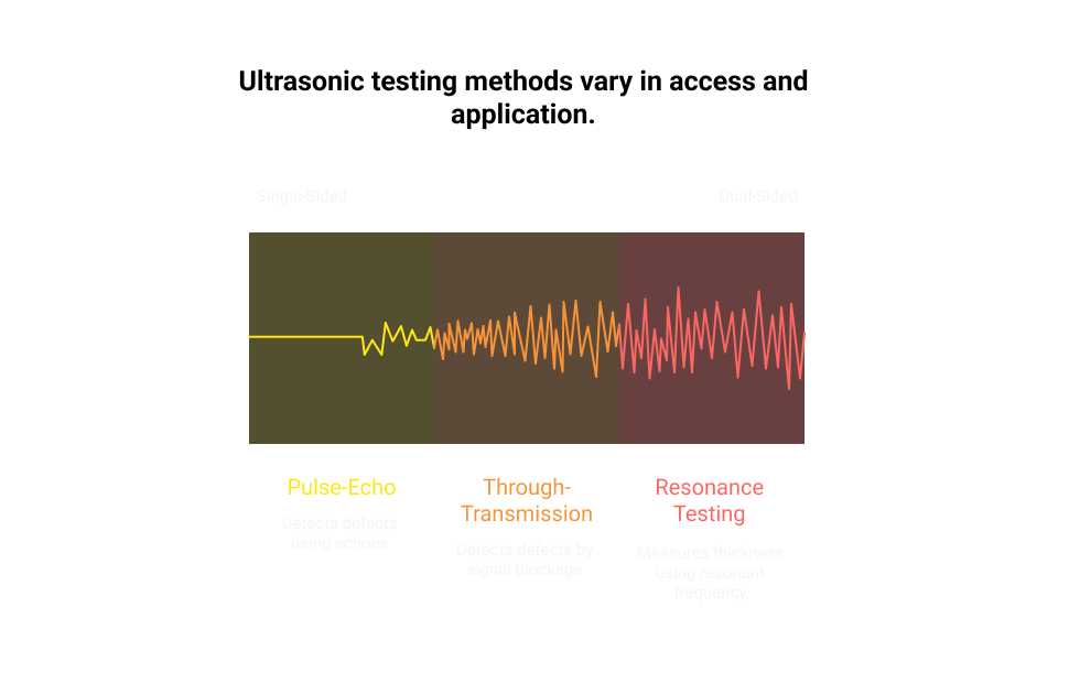
Conventional NDT ultrasonic inspection relies on several methods, each suited to specific inspection needs. Let's break down the primary approaches:
1. Pulse-Echo Testing
The workhorse of UT, pulse-echo testing uses a single transducer to send out a short burst of sound waves and listen for the echoes that bounce back. It's like pinging a submarine with sonar.
- How it Works: The transducer emits a pulse, and the time it takes for the echo to return reveals the depth of a defect or material boundary. The echo's amplitude indicates the defect's size or severity.
- Applications: Detecting cracks, porosity, or inclusions in welds, forgings, or rolled products.
- Advantages: Requires access to only one side of the material, making it perfect for pipelines or large structures.
2. Through-Transmission Testing
This method uses two transducers—one to send waves and another to receive them on the opposite side. A drop in signal strength signals a defect.
- How it Works: The transmitter sends waves through the material, and the receiver measures the transmitted energy. Defects like voids block or weaken the signal.
- Applications: Inspecting composites, adhesives, or thin plates where both sides are accessible.
- Challenges: Limited to components with dual-side access, which isn't always feasible.
3. Resonance Testing
Resonance testing is niche but valuable for measuring thickness in thin materials. It uses continuous waves to find a material's resonant frequency, which correlates to its thickness.
- How it Works: The material vibrates at specific frequencies based on its thickness. Technicians tune the frequency to calculate precise measurements.
- Applications: Measuring coatings, thin sheets, or corrosion in accessible areas.
- Limitations: Less effective for flaw detection compared to pulse-echo.
Each method has its strengths, and choosing the right one depends on the material, defect type, and inspection constraints.
The Ultrasonic Examination Procedure
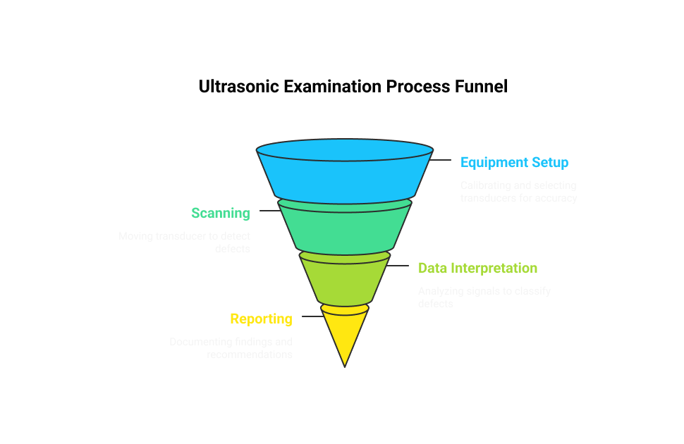
Executing an ultrasonic examination procedure is a meticulous process that demands precision and expertise. Here's how NDT professionals typically conduct a UT inspection:
1. Surface Preparation:
Clean the test surface to remove dirt, scale, or loose paint, as these can block sound waves. A smooth surface ensures good transducer contact.
Apply a couplant (gel, oil, or water) to eliminate air gaps, which disrupt sound transmission. Too much couplant can be messy, so moderation is key.
2. Equipment Setup:
Calibration: Use reference standards like calibration blocks (for example the IIW block, also designated V1, specified in ISO 2400) to set up the flaw detector. This ensures accurate measurements of distance and amplitude.
Transducer Selection: Pick a transducer based on material and defect type. For instance, low-frequency transducers (1–5 MHz) penetrate thicker materials, while high-frequency ones (10–15 MHz) excel at detecting small flaws in thin sections.
3. Scanning:
Move the transducer manually or use automated systems for consistent coverage. Watch the flaw detector's display for A-scan signals (amplitude vs. time) indicating defects or back-wall echoes.
Angle-beam transducers are often used for welds to detect misaligned or angled flaws.
4. Data Interpretation:
Analyze signal peaks to determine defect depth, size, and orientation. This step requires experience to distinguish true defects from noise caused by grain structure or geometry.
Apply the acceptance criteria set by the governing code or product standard—for example, EN 10160 for steel flat products, or the referencing code section for ASME work, such as Section VIII Division 1 or B31.3. Note that ASME Section V specifies how the examination is carried out, not what is acceptable; the acceptance criteria come from the referencing code.
5. Reporting:
Document findings in detailed reports, including A-scans, B-scans (2D cross-sections), or C-scans (plan-view maps) for clarity.
Note defect characteristics and recommend actions like repair or replacement.
This structured ultrasonic examination procedure ensures reliable results, but it's not foolproof—operator skill and equipment quality are critical.
Applications of Ultrasonic Testing
UT's versatility makes it a staple in industries where safety and reliability are non-negotiable. Here are some key applications of ultrasonic testing:
- Weld Imperfection Detection: UT excels at finding cracks, lack of fusion, or porosity in welds for pipelines, bridges, or pressure vessels.
- Corrosion and Erosion Monitoring: Measure wall thickness in pipes, tanks, or offshore platforms to track material loss over time.
- Aerospace: Inspect turbine blades, landing gear, or composite panels for delaminations or fatigue cracks that could lead to catastrophic failures.
- Manufacturing: Verify the quality of castings, forgings, or rolled products, ensuring they meet strict standards before assembly.
- Power Generation: Check boilers, steam turbines, or nuclear reactor components for flaws that could compromise safety under high pressure or temperature.
- Railways: Inspect axles, wheels, or rail tracks for fatigue cracks, ensuring safe operations.
- Marine: Evaluate ship hulls or propeller shafts for corrosion or weld imperfections.
These applications underscore UT's role as a critical tool in NDT ultrasonic inspection, delivering insights that keep industries running safely.
Advantages of Ultrasonic Testing
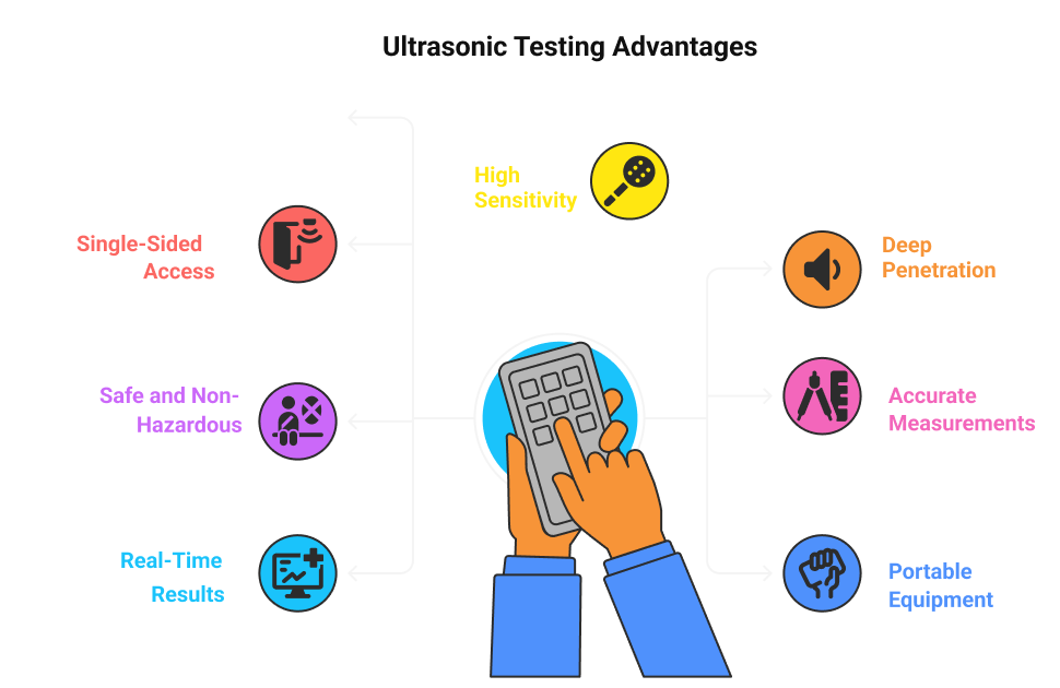
UT's popularity among NDT test types stems from its unique strengths:
- High Sensitivity: Detects minute flaws deep within a component—inclusions, voids, or lack of fusion—with better resolution than many other volumetric methods.
- Deep Penetration: Probes thick materials—several meters in fine-grained, low-attenuation components such as large forgings, though considerably less in coarse-grained material—without needing to cut or disassemble.
- Single-Sided Access: Pulse-echo testing works with access to just one side, ideal for field inspections.
- Accurate Measurements: Precisely measures defect size, depth, and material thickness.
- Safe and Non-Hazardous: No radiation risks, unlike radiography, making it safe for operators and bystanders.
- Portable Equipment: Handheld flaw detectors are lightweight and field-ready, perfect for remote sites.
- Real-Time Results: Immediate feedback on flaw detector screens speeds up decision-making.
These benefits make UT a go-to for NDT professionals seeking reliable, efficient inspections.
Limitations of Ultrasonic Testing
Despite its strengths, UT has limitations that NDT professionals must account for:
- Material Constraints: Coarse-grained materials like cast iron or austenitic stainless steel scatter sound waves, creating noise that obscures defects. Composites and non-metallics can also be challenging.
- Surface Requirements: Rough, irregular, or coated surfaces can disrupt sound transmission, requiring thorough cleaning or specialized techniques.
- Operator Dependence: Interpreting signals requires extensive training (e.g., Level II certification per ISO 9712). Misreading noise as a defect can lead to costly errors.
- Equipment Costs: High-end UT systems, especially automated ones, can be pricey, though portable units are more affordable.
- Complex Geometries: Irregular shapes or welds with complex profiles can cause unwanted reflections, complicating interpretation.
- Couplant Challenges: Applying couplant can be messy or impractical in certain environments, like high-temperature surfaces.
- Calibration Sensitivity: Inaccurate calibration (e.g., using the wrong block) can skew results, requiring strict adherence to standards.
- Near-Surface Dead Zone: The initial pulse and transducer ringdown mask a region immediately below the entry surface, so flaws close to the surface can be missed. This is why PT or MT is usually paired with UT where surface-breaking defects are a concern.
- Flaw Orientation: Detection depends on the beam meeting the reflector at a favourable angle. A planar flaw lying parallel to the beam returns little energy, which is why weld procedures specify scans from multiple angles and directions.
Understanding these limitations helps technicians mitigate risks and choose complementary NDT test types when needed.
Best Practices for Effective UT
To maximize the effectiveness of ultrasonic NDT testing, consider these practical tips:
- Prioritize Training: Certification programs (e.g., ASNT Level II or PCN) ensure technicians can interpret signals accurately and troubleshoot issues like noise.
- Select the Right Transducer: Match frequency and beam type to the job. For example, use 2 MHz for thick steel plates and 5 MHz for typical weld inspection, reserving 10 MHz for thin sections where small flaws are the concern.
- Calibrate with Precision: Use standardized blocks (e.g., V1, V2, or step wedges) and verify settings for material velocity and probe angle.
- Manage Couplant: Apply a thin, even layer to avoid air gaps without creating excess mess. Water-based couplants work well for most applications.
- Troubleshoot Noise: If signals are noisy, adjust gain, use damping, or switch to a lower-frequency transducer to improve clarity.
- Combine Methods: Pair UT with visual testing or dye penetrant for surface flaws to ensure comprehensive inspections.
- Leverage Automation: For large or repetitive jobs, automated UT systems like robotic crawlers improve consistency and speed.
- Document Thoroughly: Include screenshots of A-scans or B-scans in reports, along with clear notes on defect characteristics and standards used.
These practices help NDT professionals get reliable results and build confidence in their ultrasonic examination procedure.
Emerging Trends in Ultrasonic Testing
While conventional UT remains a cornerstone, advancements are expanding its capabilities. Phased Array Ultrasonic Testing (PAUT) uses a single probe containing many small elements, pulsed with calculated time delays, to create steerable beams, producing detailed 2D and 3D images of defects. Time-of-Flight Diffraction (TOFD) enhances accuracy for weld inspections by timing the signals diffracted from crack tips between a separate transmitter and receiver. Guided wave UT is gaining traction for inspecting long structures like pipelines without extensive access.
Automation and AI are also transforming UT. Automated scanners reduce human error, while AI algorithms analyze signals in real time, flagging defects with high accuracy. For NDT professionals, staying current on these trends—through training or industry events—ensures you're ready for the future.
Case Study: UT in Action
Consider a real-world scenario: inspecting a gas pipeline weld. A technician uses a 5 MHz angle-beam transducer in pulse-echo mode to scan for lack of fusion. After calibrating with an IIW block, they apply couplant and move the probe along the weld. The A-scan shows a strong echo at a 20 mm sound path, which converts to a depth consistent with the weld fusion face. By adjusting the probe angle and sizing the indication against the acceptance criteria in the governing code, the technician confirms lack of fusion and recommends repair. This showcases how NDT ultrasonic inspection delivers actionable insights in high-stakes environments.
Conclusion
Conventional UT remains the default volumetric method across most industries for a straightforward reason: it gives depth, position and size from one side of a component, in real time, without ionising radiation. Nothing else in the conventional toolkit does all four.
Its reliability, though, comes from understanding rather than equipment. The wave mode carrying the energy, the refracted angle relative to the expected flaw orientation, the grain structure of the material, whether the reflector sits in the near field or the far field — these determine whether an inspection finds what it is looking for. A calibrated instrument in the hands of an operator who has not thought through beam angle and flaw orientation will produce a clean, confident, empty scan.
The limitations are equally worth respecting. Coarse grain, awkward geometry, the near-surface dead zone and unfavourably oriented planar defects are all situations where UT alone is the wrong answer and a complementary method belongs in the procedure. Knowing when not to rely on UT is as much a part of competence as knowing how to run it.
PAUT, TOFD and guided wave techniques continue to extend what is achievable, but each is built on the same physics set out above. Technicians who are solid on the fundamentals adopt them quickly; those who are not tend to struggle with the interpretation regardless of how capable the instrument is.
FAQs (Frequently Asked Questions)
1. What is Ultrasonic Testing (UT) and why is it important in non-destructive testing?
Ans: Ultrasonic Testing (UT) is a non-destructive testing method that uses high-frequency sound waves to detect flaws or characterize materials. It is crucial in industries like manufacturing, aerospace, and construction for ensuring the integrity and safety of components without causing damage.
2. What are the main methods used in conventional Ultrasonic Testing?
Ans: The primary methods of conventional Ultrasonic Testing include Pulse-Echo Testing, Through-Transmission Testing, and Resonance Testing. Each method operates differently; for example, Pulse-Echo sends sound waves and listens for echoes to detect flaws, while Through-Transmission measures sound passing through a material.
3. In which applications is conventional Ultrasonic Testing commonly used?
Ans: Conventional UT is widely applied in weld inspection, corrosion monitoring, and aerospace component inspection. These applications benefit from UT's ability to detect internal defects and assess material conditions effectively.
4. What are the advantages and limitations of using conventional Ultrasonic Testing?
Ans: Advantages of UT include high sensitivity to small flaws and the capability to penetrate thick materials. However, limitations exist, such as dependency on operator skill level, material constraints, and challenges with complex geometries that may affect accuracy.
5. What best practices ensure effective conventional Ultrasonic Testing?
Ans: Effective UT requires proper training and certification for operators to guarantee accurate results and safety. Additionally, selecting appropriate transducers, frequencies, and beam angles tailored to specific testing scenarios enhances inspection effectiveness.
6. What emerging technologies are enhancing Ultrasonic Testing capabilities?
Ans: Advanced techniques like Phased Array Ultrasonic Testing (PAUT) and Time-of-Flight Diffraction (TOFD) are gaining popularity due to their improved detection capabilities. These technologies offer enhanced imaging and flaw characterization but also present challenges such as increased complexity and cost.