Table of Contents:
- Introduction: Evolving Precision in Ultrasonic Testing
- Fundamentals: How PAUT and TOFD Work
- Imaging Capabilities and Data Interpretation
- Detection Capabilities and Sensitivity
- Coverage Area and Inspection Speed
- Equipment and Cost Considerations
- Skill Level and Operator Dependency
- Limitations and Challenges
- Applications in Industry
- Compliance and Standards
- Conclusion: Choosing Between PAUT and TOFD
- FAQs
Introduction: Evolving Precision in Ultrasonic Testing
A skilled NDT expert waves a probe on a welded pipe in the eerie light of a refinery turnabout. More time passes, the phased array scan compiling its image. A few seconds are followed by a second confirmation ping of a Time-of-Flight Diffraction (TOFD) scan. The two tools convey the same emotions such as wall thinning and creeping planar flaw approaching the breach trigger. The statistics cannot be denied and the intervention is overdue. This is not fortune; it is an outcome of the right decision of selecting the inspection method in the required moment.
In today’s industrial world, where safety, uptime, and compliance are non-negotiable, ultrasonic testing plays a vital role in non-destructive evaluation. However a modern infrastructure no longer requires traditional methods to fulfill accuracy requirements. That’s why advanced technologies like Phased Array Ultrasonic Testing (PAUT) and Time-of-Flight Diffraction (TOFD) have become essential tools in the NDT professional’s arsenal.
Though both PAUT and TOFD rely on principles of the ultrasonics, they are essentially different methods. They possess their own special benefits: PAUT is quite effective at imaging and flaw detection over complex geometries; TOFD is worshiped in being very precise in sizing cracks and detecting through-wall defects. Decisions on using one of them or knowing when to employ a combination of both can greatly affect the consistency of the findings of an inspection.
In this article, we’ll break down the difference between PAUT and TOFD using a technical yet accessible approach backed by field experience. You will find out how they work, their advantages and disadvantages and their application depending on inspection requirements.
Whether you’re an NDT technician evaluating welds, a researcher developing inspection protocols, or a plant manager seeking to reduce downtime, this guide will help you understand the practical applications and limitations of PAUT vs TOFD—so you can make smarter, safer, and more cost-effective inspection decisions.
Fundamentals: How PAUT and TOFD Work
1. Phased Array Ultrasonic Testing (PAUT)
PAUT works with a combination of several tiny ultrasonic components within one probe. All elements may be pulsed (timed) individually making the beam electronically steerable, focusable, and sweepable through the test material. Through this dynamic control PAUT is able to scan a complex geometry with high precision and quicker area coverage.
- They (beam steering and focusing) enable the inspection of various angles of a fixed probe.
- Sectorial scanning gives the visual pictures of the faults in real-time.
- Effective at locating a weakness in the welds such as crack, lack fusion, or porosity.
2. Time-of-Flight Diffraction (TOFD)
TOFD, in its turn, is founded on the diffraction of ultrasound waves. It involves a transmitter and a receiver on either side of the weld. As the ultrasonic pulse runs into the discontinuity some of the energy is deflected by the ends of the flaws. This difference between the time of arrival of these diffracted signals to the receiver is what is utilized to calculate both the location as well as the size of the flaw.
- Very precise in the measurement of defects especially the cracks.
- Depth information in time-based signal measurement is very accurate.
- Puts into use longitudinal waves as opposed to reflected/refracted waves.
Imaging Capabilities and Data Interpretation
Among the significant aspects of PAUT and TOFD differences is presentation and interpretation of the data.
1. PAUT Imaging
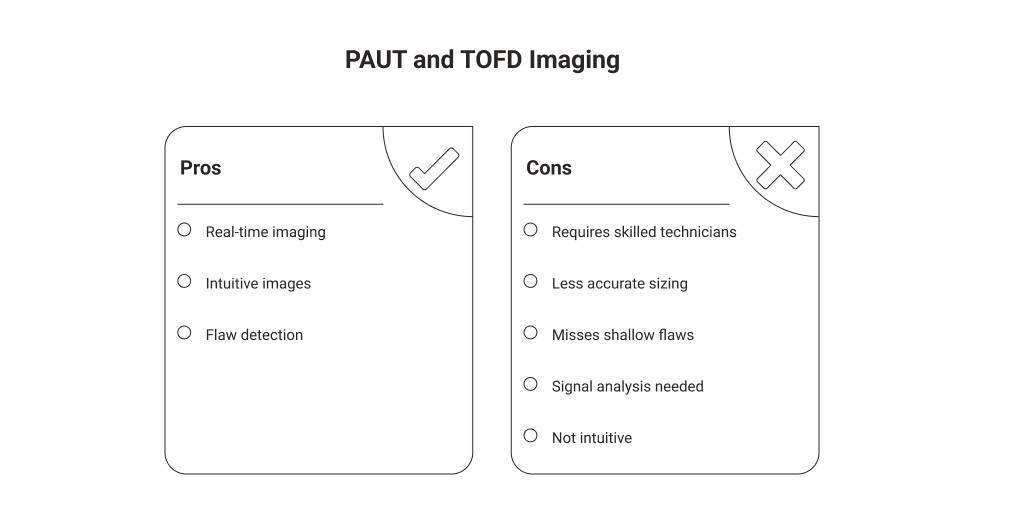
PAUT offers the visualization of images in high-resolution, attending to the medical ultrasound scan. The operator is able to see sectorial scans (S-scans) and B-scans showing the internal structure of the material in a graphic form. The images are also intuitive and this enables quick study of the image and aids in the recognition of complex geometries.
- Provides real time imaging.
- More easily interpreted by surface-breaking flaws or volumetric flaws.
- Demands competent technicians in order to be evaluated to the full extent.
2. TOFD Imaging
TOFD monitors the associated time or flight of diffracted happenings to form a gray-scale image. These pictures are not as intuitive as PAUT images, but they are highly reliable in giving the tip-diffracted signals especially in crack sizing.
- Great accuracy in sizing flaws.
- Can fail to see minor or shallow flaws because of the diffraction rule.
- Better an analysis of the signals than a visualizing it.
Detection Capabilities and Sensitivity
- PAUT Detection Strengths
An outstanding product on volumetric flaws, porosity as well as lack of fusion and slag inclusions.
Flexible on geometries and materials.
Great sensitivity, variable depth focal and beam steering.
- TOFD Detection Strengths
Excellent in respect of planar defects such as cracks and poor fusion.
Higher quality of depth sizing.
Unsensitive to flaw orientation, hence being perfect to sense flaws regardless of orientation.
Important distinctions: PAUT out-performs TOFD best in imaging and volume coverage where TOFD has no competitor when it comes to quantitative flaw sizing particularly in through-thickness cracks.
Coverage Area and Inspection Speed
- PAUT Efficiency
Enables large area coverage with a single scan with its sectorial scanning into use.
Fast to set up simple welds, and longer the more complex.
There may be the need to take multiple scans to capture flaws with varied positions.
- TOFD Efficiency
This offers entire through-wall coverage on one pass.
Once calibrated and aligned the high-speed inspection will be made.
When setting up, the probes should be properly aligned and spaced (usually 10 to 100 mm with regards to material thickness).
Possibly in the high-production environment where speed and reliability are the factor in demand, use of a combination of both PAUT and TOFD usually yields the best solution.
Equipment and Cost Considerations
- PAUT Equipment
Is a phase-array-probe, pulser/receiver and software.
Needs higher calibration and trained staff.
The array and imaging technologies and capabilities may lead to more expensive equipment.
- TOFD Equipment
It needs two standard UT probes, a digitizer and TOFD specific software.
Cheaper hardware, yet requires good calibration and scanning.
The generation of longitudinal waves streamlines the process of making a few choices related to the use of probes.
Although PAUT is usually more expensive to set up initially, TOFD requires greater alignment of the mechanical system, and may require supplementary scanning to cover small or shallow defects.
Skill Level and Operator Dependency
1. PAUT Requirements
The operators should be trained to operate in setting up the beam, angle selection and software analysis.
More convenient to the operators who know the traditional UT.
2. TOFD Requirements
Requires solid knowledge of wave physics, signal processing, and flaw diffraction.
Operators should be able to interpret the D-scan gray-scale images which cannot be as visual as the PAUT scans..
In both techniques, the ability of the operator is an important issue- TOFD, however, may demand greater knowledge of signal handling and timing measurement.
Limitations and Challenges
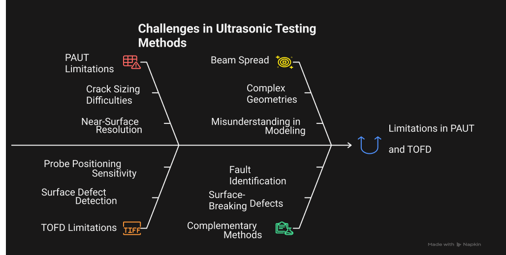
1. PAUT Limitations
Difficulties in sizing cracks as accurately as possible particularly tip-to-tip sizing.
Resolution in the near-surface is restricted on wedge and frequency.
Unless well focused, beam spread can cause misunderstanding during the model of complex geometries.
2. TOFD Limitations
Not the best option in finding surface-breaking defects or very small discontinuities.
Very sensitive to the correct positioning of the probe and condition of the surface.
May need to be complemented by methods such as PAUT to identify types of faults.
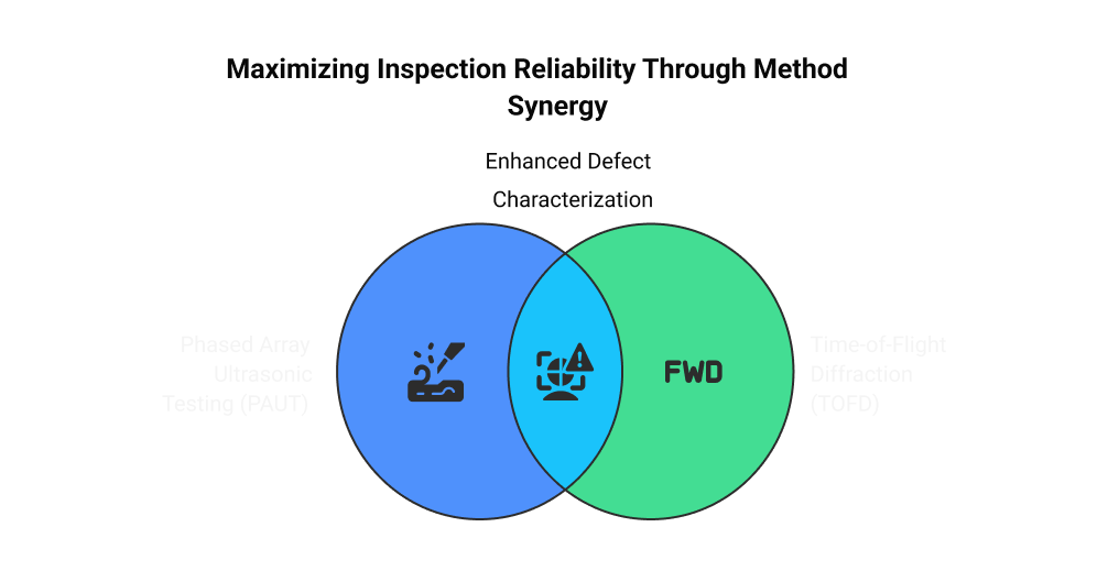
This is an indication of the fact that a lot of high critical applications utilize both methods simultaneously: PAUT to detect and TOFD follow up to achieve confirmation and size.
Applications in Industry
Both of the methods have gained popularity in most of the industries, including:
- Oil & Gas: Pipeline, pressure vessel and weld inspection.
- Power Generation: To assess components of boilers and turbines.
- Aerospace: Particularly PAUT, applicable in the inspection of composites and in-service structure.
- Structural Steel & Fabrication: TOFD is particularly popular to size flaws in thick welds.
The choice between PAUT versus TOFD often comes down to application needs: detection vs. sizing, geometry complexity, and flaw type.
Compliance and Standards
Both PAUT and TOFD are recognized and standardized in major international codes:
- ASME Section V
- API 1104
- ISO 13588 (PAUT)
- ISO 10863 (TOFD)
These codes present standards of calibration, equipment, scanning techniques, data interpretation and documentations. Adhering to these standards makes the reliability and compliance to be in line with industry standards.
Conclusion: Choosing Between PAUT and TOFD
Choosing between Phased Array Ultrasonic Testing (PAUT) and Time-of-Flight Diffraction (TOFD) ultimately depends on the inspection goal, type of defect, and asset geometry. PAUT is also well versatile as detecting volumetric defects and it provides real-time imaging which improves operator interpretation. Conversely TOFD is very effective in measuring and also to identify planar defects particularly cracks in an astonishing way as it is a time-based measurement method.
Although both methods are powerful by themselves, they are not one-size-fits all as well. TOFD could miss near-surface defects or very small indications, PAUT may not be able to size the crack tip. That is why the combination of these two methods is common in many inspection strategies of high-stakes enterprises, like oil and gas, or power generation. The combination provides an all-embracing fault finding and correct sizing, and the inspection outcomes are more certain.
With the combination of PAUT and TOFD, the NDT professionals overcome the limitations of both directions and provide the maximum advantage of both techniques, which can enhance the degree of reliability, be more consistent with international codes, and make more informed maintenance decisions.
FAQs:
What is the difference between phased array ultrasonic testing and TOFD?
Ans: While Phased Array uses numerous transducers to emit ultrasonic waves at different angles, TOFD uses diffracted sound waves, depending on diffraction to detect defect edges. This distinction impacts each method's efficacy in specific inspection settings as well as its sensitivity to specific defect kinds.
What is the difference between normal UT and PAUT?
Ans: PAUT covers a large area in a comparatively short amount of time, giving you a detailed image of the internal defects within a building. UT can then be used in smaller or more difficult-to-reach communities.
What is ultrasonic time of flight?
Ans: Ultrasonic distance measurement produces a brief, high-frequency sound pulse that is over the human hearing threshold on a cyclical basis. The pulse time-of-flight measurement for the sound between the object and the sensor can be used to calculate the distance to the object.
What is time-of-flight diffraction?
Ans: Time-of-Flight Diffraction (TOFD) is an advanced ultrasonic testing (UT) technique that is mostly used for non-destructive testing of structural materials, including welds, especially for sizing and fault detection. It makes use of the diffraction of ultrasonic waves from defect points to precisely locate and measure defects like voids and cracks.
What is the principle of ToF?
Ans: The foundation of the time-of-flight principle is the measurement of the wave's transit time from a source (a time-of-flight sensor) to an object and back.


