Ultrasonic NDT
Inspection of Composite Materials
Published on 4th January 2021

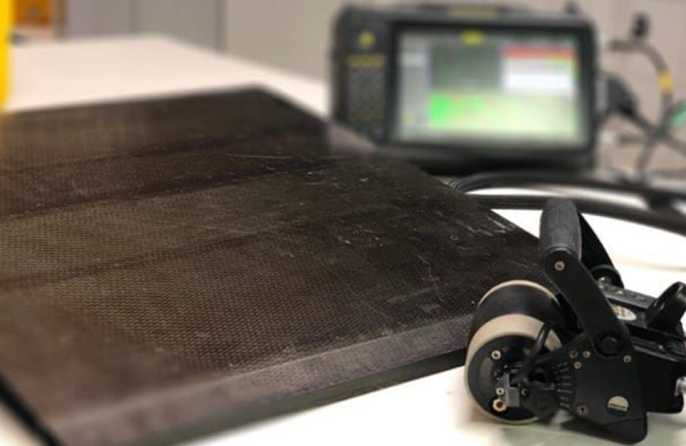
Increasingly composites are being used to replace traditional materials of construction. Amongst a number of advantages composites provide high strength with low weight and corrosion resistance. However, quality assessment of composite parts is challenging.
Adopting recognised ultrasonic techniques to perform NDT inspection of composite components can provide reliable and repeatable results for both in-line and maintenance examination.
A linear scan (0-degree) inspection is highly recommended. Composites are anisotropic, meaning that they have different properties when measured in different axis, thus the velocity of transverse waves varies with the beam angle, making angular scans inappropriate.
Characteristics of the Flaws
Defects may originate from mishandling or abuse, but are also unintentionally created at the time of production. Lack of detection may lead to a much shorter part lifespan and possible failure in service.
Fabrication defects:
- Insertion of unknown material between plies
- Poor bonding (lack of adhesive)
- Layers overlapping
- Porosities
- De-laminations (caused by human manipulation or machining)
Mechanical damage defects:
- Stress, Fatigue and Shearing
- Impacts
- Heat
- Abrasion
- Chemical Reaction
Through transmission inspection:
This approach is widely spread for honeycomb assessment. Such structures can be inspected with two set of dry probes apart from each other. Such approach it able to detect disbound of the panel from the core.
Moreover, it is possible to inspect the honeycomb itself (In between the Panel) using low frequency bandwidth with the Sonatest Prisma, D-70, MS-700. (< 1MHz). This Dryscan feature verifies if the bond and honeycomb is homogeneous.
* Did you know that with the Prisma instrument you can recorded this information
Pulse-echo
Amplitude based or Time of flight based?
The C-scan can display the recorded information according to the time-of-flight or the signal amplitude. For composite inspection, both information are important because they highlight defect zones differently. Amplitude base C-scan gate positioning would often monitor the back-wall echo of the part. This information would be very sensitive to coupling variation, disbounding, porosity or anything that would affect signal strength somehow … Time of flight C-scan gate positioning would be position in between the backwall echo and the Emission echo. This view is generally less sensitive than the previous one however it keeps the Depth information of the flaw.
Amplitude C-Scan of composite material
Depth C-Scan of composite material
Sizing Defects
Sonatest developed a unique and automated indication sizing too, wich allow the inspector to quickly find and size unforeseeable indication shape. UTmap defective zone algorithms based on amplitude or time-of-flight fully editable criteria. The algorithm give visual feedback of the defective area while sending dimensional information about the defect such as depth, width, length, global area…
Any UT Data can be exported in PDF or CSV
Industries
- Automotive
- Aerospace
- Energy
Typical Parts
- Honeycomb Structure
- Panel
- Blade
- Frame
Inspection Technique
- Phased Array
- L-Scan (Linear Scan)
- Automated or Manual
- Immersion
Features & Benefits
- Higher productivity
- Reduce probe swapping
- 100% coverage to increase Probability of Detection
- Full data recording
- Wideband filters up to 27MHz (VEO+)
- Portable and safe (comparable to X-Ray)
Recommended Package
- Rsflite/Veo+/Prisma
- Utmap/Utstudio+
- WP2 2.25 to 10MHz or
- D5A 5MHz with encoder or 10 MHz Stringer
For further information or support, please contact the Sonatest Applications Team: applications@sonatest.com


