Ultrasonic NDT
Friction Stir Welds Inspection
Published on 8th April 2021

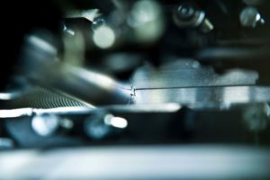
Fabrication of the core stage liquid hydrogen tank on NASA's Space Launch System required more than 2.7km of friction stir welds to be inspected with a combination of ultrasound and radiography Credit: NASA
Aerospace manufacturers use friction stir welds (FSW) to fabricate many of their biggest aluminium alloy structures, from fuselage panels and wing assemblies on aircraft to rocket boosters and fuel tanks on launch vehicles.
It’s a highly automated joining process that uses a machine to clamp two workpieces together and plunge a rotating spindle into the joint line. The spinning action generates friction and heat, causing the adjacent metals to become plastic. Material flows from the front of the tool to the trailing edge, where the grains mix and recrystallise to form a strong, efficient bond.
To a qualified NDT technician, a typical FSW lap-joint or butt-weld isn’t technically difficult to test. The bigger issue is the sheer size and scope of the inspection. Welds may run dozens of metres across complex geometries. Scanning with conventional NDT methods can be time-consuming when there’s a need for inspections that are quick to set up and complete while delivering a high probability of detection.
Weld profiles
A friction stir weld has three distinct zones: an outer heat affected zone (HAZ) where the metal’s properties are affected but no deformation occurs; an inner thermo-mechanically affected zone (TMAZ) where grains are deformed but not mixed; and a stir zone or ‘nugget’ comprising very fine equiaxed grains.
Because the joining process involves low peak temperatures and the materials remain in a solid state throughout, a stir weld isn’t susceptible to porosity, cracking, distortion, and other discontinuities that occur when metals are melted and then solidify. Most FSW flaws are related to setup issues: improper spindle rotation speeds, rates of travel, lack of penetration or forging pressure, and gaps along the seam from poor fit-up or clamping can result in excessive or insufficient heat and an insufficient bond.
The bulkhead and nosecone of NASA’s Orion spacecraft are joined using friction stir welding Credit: NASA
When manufacturing flaws do occur, they fall into several categories: volumetric voids, like ‘wormholes’ and cavities; joint-line flaws like ‘kissing bonds’, where two butted materials fail to coalesce completely; and ‘hooking’, an uplift of surface oxides on the advancing side or retreating side of a lap weld.
Eddy current array
Speed is an advantage in stir welding, so any inspection method should be efficient as well. Because penetrant testing and radiography can be time-consuming and disruptive to fabrication, digital tools can deliver the speed and probability of detection that manufacturers value.
Eddy current array (ECA) is a fast, accurate, chemical-free method for detecting surface and sub-surface indications that are too small to see with the naked eye, including cracks, pits, corrosion, and damage due to impact or fatigue.
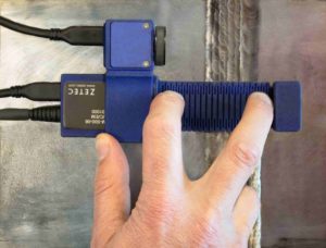
The coils in an eddy current probe need to be close to the material for accurate flaw detection and signal quality
An ECA inspection involves using a handheld instrument and a probe with multiple coils in it that fire electronic currents into the weld and surrounding material. The coils activate at coordinated times and can capture more information in a single pass compared to conventional eddy current probes.
The C-Scan capability of ECA instruments provides instant visual feedback to the technician, increasing the probability of detection, and creates a digital record that can be stored, analysed, and compared against a history of test results. Furthermore, the improved signal-to-noise ratio (SNR) of today’s ECA technology enhances its ability to detect the very small flaws and loss of material that can occur in stir welds.
One practical limitation of eddy current technology is that the coils in the probe need to be close to the material, which a challenge because of the various geometries, non-uniform surfaces, and hard-to-reach areas on a large component.
Some ECA probes are flexible, which allows the coils to bend and remain nominally perpendicular to a rough, irregular, or complex-shaped surface. In most cases, a flexible surface array probe with just 5cm of coverage can encapsulate the HAZ, transition zone, and stir zone in a single pass.
Phased-array UT
Ultrasonic testing (UT) uses high-frequency sound energy to indicate flaws both on and beneath the surface. Phased-array UT is an advanced inspection method that uses multiple individual elements (typically from 16 to 64) in a single probe. By exciting each element in a controlled manner, a phased-array UT instrument can produce a precise beam shape and generate views of a flaw with greater speed and accuracy. Like ECA, the results are immediate, digital, and detailed on a C-Scan. Because of advancements in software, portability, and battery life, technicians can bring this computing power virtually anywhere.
With a portable phased-array UT instrument and dual (2D) matrix array probe assemblies, NDT technicians can build efficient scan plans; conduct lateral scans and create 3D representations of the weld; and detect mis-oriented and transverse flaws in lap and butt welds.
Covering the entirety of a stir weld with phased-array UT requires multiple beam angles, however, can add steps to the inspection process.
For a butt-joint weld, the recommended technique for transverse flaws involves linear electronic scanning with two different refracted angle orientations: a +45° shear wave and a symmetrical -45° shear wave (+20° and -20° incident wave angles in immersion). In the case of a lap-joint weld, the same two beam angles (+45°SW and -45°SW) are used in conjunction with a 0° longitudinal wave, which is the ideal angle for detecting joint-line flaws.
Performing the inspection with a standard single 64-element probe requires multiple setups and scanning sequences. A lap-joint inspection would involve separate sequences at +45°SW, 0°LW, -45°SW, with the technician stopping in between scans to realign and recalibrate the probe. A butt joint would require two separate scans at +45°SW and -45°SW.
Interrupting the test to manipulate the probe orientation every time another refracted angle is required is tedious but necessary due to the limited steering capability of a probe that’s not designed for FSW inspections.
An alternative is a 1D linear array probe with 128 elements that can simultaneously generate 0°LW and 45°SW beams for flaws parallel to the weld centre line without probe inclination, and 45°SW for detection of transverse flaws when inclined in the secondary plane. This type of optimised probe can obtain full volumetric coverage of the weld zone in a single scanning sequence and allow better detection of skewed flaws and accurate sizing compared to other solutions.
Because all required refracted angles are generated with a single probe positioned at a normal incidence with respect to the inspected specimen surface, this alone simplifies the probe installation and alignment method since all that’s now required is to install it in the 0° scanner head.
The latest digital tools, software, and probes can help manufacturers, MRO managers, and NDT technicians save time and money, inspect more areas faster, and maximise the performance of assets in the air.