Back to Companies

Gamma-Tech Inspection Ltd.

Gamma-Tech has aspired to achieve a level of customer care unheard of in the NDT industry and the results speak for themselves.

Service

Canada

Visit Website
Overview

Gamma-Tech Inspection Ltd. (GTIL) has put customer care first. Founder and current owner Debra Ross knew that NDT clients were eager for a company capable of promptly providing the highest quality testing services and at a reasonable price. Gamma-Tech has aspired to achieve a level of customer care unheard of in the NDT industry and the results speak for themselves.

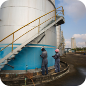
Gamma-Tech’s commitment to customer service is supported by our dedication to understanding our client's needs, function, quality assurance and safety programs that encompass state-of-the-art equipment and technology. With a first-rate reputation, Gamma-Tech provides a full suite of NDT services to the oilfield and construction industry. We proudly cater to a long list of loyal clients.

Since its founding in 2002, Gamma-Tech has continuously increased its expertise and experience in all aspects of our industry, providing service based on the latest technology and equipment available to its clients.

Products & Services
Magnetic Particle Testing

MPT Fluorescent Fluorescent Magnetic Particles (requires a black light) are used in the detection of SURFACE and SUBSURFACE indications in FERROUS materials. Each product can be used for either WET or DRY methods of magnetic particle inspections. Particle size is controlled to ensure maximum sensitivity. Meets major specifications. Provides accurate, reliable crack detection results in the following applications:

  • Automotive Components
  • Manufacturers
  • Welds
  • Lifting Devices
  • Test Labs
  • Fabrication Shops
  • Ski Lift Maintenance
  • Steel Mills
  • Pipelines
  • Railroads
  • Plant Maintenance

MPT Visual
Visible (daylight) Magnetic Particles are used for magnetic particle inspection method in the detection of SURFACE and SUBSURFACE indications in FERROUS materials. Each product can be used for either WET or DRY methods of magnetic particle inspections. Particle size is controlled to ensure maximum sensitivity. Meets major specifications. Provides accurate, reliable crack detection results in the following applications:

  • Automotive Components
  • Manufacturers
  • Rebuilders
  • Welds
  • Lifting Devices
  • Pipelines
  • Railroads
  • Test Labs
  • Military
  • Amusement Ride Maintenance
  • Fabrication Shops
  • Ski Lift Maintenance
  • Steel Mills
  • Plant Maintenance
Gamma Radiography

Industrial radiography is used for a variety of applications but is commonly performed using two different sources of radiation, X-ray and Gamma ray sources.

The choice of radiation sources and their strength depends on a variety of factors including the size of the component and the material thickness. Within the broad group of X-ray and Gamma ray sources are a variety of exposure device choices with varying radiation strengths. Gamma-Tech radiographic capabilities use portable gamma-ray exposure devices for field weld applications up to 7″ tk. wall material inspection. Gamma sources vary from very low-level Iridium (IR192 – up to 3″ tk. steel) sources used for a variety of weld inspections, to Cobalt (Co 60 – up to 7″ tk. steel) inspections for thick component testing.

There are many advantages to radiography including inspection of a wide variety of material types with varying density, the ability to inspect assembled components, minimum surface preparation required, sensitivity to changes in thickness corrosion, voids, cracks and material density changes, the ability to detect both surface and subsurface defects and the ability to provide a permanent record of the inspection.

Ultrasonic Straight Beam Testing

Traditional Ultrasonic inspection uses high-frequency sound energy to conduct examinations and perform measurements. Considerable information may be gathered during ultrasonic testing such as the presence of discontinuities, material or coating thickness. The detection and location of discontinuities are enabled by the interpretation of ultrasonic wave reflections generated by a transducer. These waves are introduced into a material and travel in a straight line and at a constant speed until they encounter a surface. The surface interface causes some of the wave energy to be reflected and the rest of it to be transmitted. The amount of reflected vs. transmitted energy is detected and provides information on the size of the reflector, and therefore the discontinuity encountered.

Three basic ultrasonic techniques are commonly used:

Normal/Angle Beam – Normal beam testing uses a sound beam that is introduced at 90 degrees to the surface – for thickness testing, while angle beam utilizes a beam that is introduced into the specimen at some angle other than 90 degrees – for defect location. The choice between the two is made based on the orientation of the feature of interest so that the sound may produce the largest reflection from the feature and obstructions on the surface of the specimen that must be avoided.

Some of the most common Ultrasonic applications are:

Flaw detection (cracks, inclusions, porosity, delaminating etc.)
Erosion/Corrosion thickness gauging Info from ultrasonic inspection can be presented in a number of formats: A-Scan displays the amount of received ultrasonic energy as a function of time Be-Scan displays a profile view (cross-sectional) of a specimen
C-Scan displays a plan type view of the specimen and discontinuities Hybrid/Stitched displays a C-Scan plan view with A and/or B Scan views along with C-Scan views that have been woven together to illustrate a clearer picture of the damaged areas of a specimen. The stitched views are used for larger specimens and surface areas.

Some of the major advantages of ultrasonic testing are:

Detects surface and subsurface defects Depth of penetration vs. other test methods are superior Only single-sided access is required with a pulse-echo technique High accuracy regarding estimating discontinuity size and shape Minimal specimen preparation is required Instantaneous results produced by using electronic equipment Detailed images can be produced with automated systems.

Major limitations of ultrasonic testing are:

The surface must be accessible. Skill training is more extensive than with some other methods for personnel. Normally requires couplant to promote sound transfer. Surface roughness, complex geometries, small parts or exceptionally thin materials are difficult to inspect. Coarse-grained material ie. Cast iron is difficult to inspect due to low sound transmission and high signal noise. Linear defects oriented parallel to the sound beam go undetected. Reference standards are required for equipment calibration for each item tested.

OnestopNDT
OnestopNDT OnestopNDT OnestopNDT
OnestopNDT

Step 1 - please enter your Personal details.

Step 2 - please upload your Resume.

Thank you for submitting.

Tree PNG back

Companies

Tree PNG back

Articles

Webinars

Webinars

Tree PNG back

Jobs

Application Notes

News