Back to Companies

BCS NDT

BCS NDT was created in 2016 in Italy and operates in the Non-Destructive Testing field for the Oil&Gas and Energy sectors worldwide. The company offers welding and NDT engineering support, NDT consultancy, NDT services and training.

Service

Italy

Visit Website
Overview

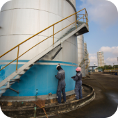
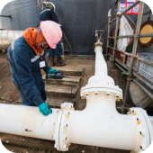
BCS NDT is an Italian company established in 2016 performing non-destructive testing (NDT) worldwide, onshore and offshore, with offices in Italy, Kazakhstan and South Korea. BCS NDT operates in Oil and gas, manufacturing and mining sectors using conventional and advanced NDT methods. The variety of NDT testing ranges from advanced techniques to conventional techniques such as:

Manual Ultrasonic Testing (MUT), Magnetic Particle Testing (MT), Dye Penetrant Testing (PT), Visual Testing (VT). Advanced methods are Phased Array Ultrasonic Testing (PAUT), Automated Ultrasonic Testing (AUT), Time of Flight Diffraction (TOFD) and Eddy Current Array (ECA). BCS NDT has an extensive track record in inspecting onshore and offshore pipelines and piping systems (spool, risers, jumpers) with advanced NDE techniques, forged items, and structures. Materials inspected spread from carbon steel to different types of corrosion-resistant alloys (CRA).

Products & Services
Phased Array Ultrasonic Testing (PAUT)

Phased array inspections are done using a probe with multiple elements that can be individually activated. By applying appropriate delays, a Phased Array is capable of generating an ultrasonic beam, modelling it according to the desired characteristics of aperture, angle and focus (electronic beam formation). The focal law may also be dynamically modified between pulses, thereby allowing effective movement of the scan beam (electronic scanning).

Each element of the Array acts as a punctiform source of ultrasonic waves when receiving the energizing pulse. When multiple elements are energized, the individual waves combine according to the principle of interference and generate a resulting wavefront. A flat wavefront is generated if energizing pulses are synchronous. The introduction of time delays in pulsations alters the interference processes between elementary waves. These time delays can be adjusted to give an adaptive Phased Array that generates beams with the required direction (angle) and focus.

An angled beam is achieved by applying a constant pulse time delay to consecutive Array elements (linear focal law).

Focusing is obtained by adjusting the pulse time delays of the elements to achieve a parabola-shaped sequence, symmetrical to the emitting Array (quadratic focal law). This allows the Phased Array to generate a focused beam at any depth (within a near field)

The resulting data can be combined to form a visual image representing a slice through the part being inspected. Data acquired by the Phased Array during scanning can be video displayed in real-time in all conventional formats used by digital instruments: A-scan, B-scan, C-scan and D-scan.

Automated Ultrasonic Testing (AUT)

Origins of the method date back to 1959 but practical field trials were not carried out until 1972. At that time operators began to investigate the feasibility of using mechanised welding techniques to replace the traditional manual Shielded Metal Arc Welding process. When evaluating the welding process, it was determined that parts of the weld bevel were poorly inspected by the traditional X-radiography which relies on defect orientation parallel to the beam to permit detection. To address this shortcoming they initiated a program to develop an automated ultrasonic inspection system.

Ultrasonic Testing

High-frequency sound is introduced into the part being inspected and if the sound hits a material with a different acoustic impedance (material density and acoustic velocity), some of the sounds will reflect to the sending unit and can be presented on a visual display.  By knowing the speed of the sound in the part and the time required for the sound to return to the sending unit, the distance to the reflector can be calculated.

The most common sound frequencies used in UT are between 1.0 and 10.0 MHz, which are too high to be heard and do not travel through the air.  The lower frequencies have greater penetrating power but less sensitivity, i.e. less ability to detect small indications, while higher frequencies don’t penetrate as deeply but can detect smaller indications.

The two most common types of sound waves used in industrial applications are compression (longitudinal) waves and shear (transverse) waves.  Shear waves travel at approximately half the speed of longitudinal waves.

Sound is introduced into the part using an ultrasonic transducer (“probe”) that converts electrical pulses into mechanical waves, and then converts returning sound back into electric impulses. This signal can be displayed as a visual representation on a digital or LCD screen.  The distance from the transducer to the reflector can be determined. The signal can also be interpreted by operators to determine the type of discontinuity (lack of fusions, slag, lack of root penetration, missed edge, porosity, cracks, segregations).  Because ultrasound will not travel through air a “couplant” is used between the face of the transducer and the surface of the part to allow the sound to propagate into the part.

Internal Rotating Inspection System (IRIS)

IRIS is an ultrasonic technique applied for the inspection of the remaining wall thickness of tubes. It is more accurate than other tube inspections and returns information on the geometry of the defect and remaining wall thickness. It is often used in conjunction with Eddy Current or Remote Field Testing.

OnestopNDT
OnestopNDT OnestopNDT OnestopNDT
OnestopNDT

Step 1 - please enter your Personal details.

Step 2 - please upload your Resume.

Thank you for submitting.

Tree PNG back

Companies

Tree PNG back

Articles

Webinars

Webinars

Tree PNG back

Jobs

Application Notes

News