
Using the correct modality of condition monitoring is critical to ensure an asset or process’s complete condition health assessment. Sometimes, feedback from multiple testing modalities is essential for accurate condition valuation. A multi-inspection approach to condition monitoring increases the chances of discovering multiple failure modes and detecting them early enough to make the necessary repairs before they become catastrophic.
Predictive Maintenance
The sweet spot for a maintenance program falls between the “degradation start” point and the “potential failure” point of an asset’s life (see chart below). Work performed on the equipment during the “normal state” period might be effective for asset health and facility uptime, producing the desired outcome. However, it is less efficient because maintenance resources are consumed on equipment that may not require upkeep or repair. Any work or investment in healthy machines in the “normal state” produces a certain amount of waste.
Alternatively, maintenance efforts and costs become reactive if the machine asset condition is allowed to degrade beyond the “potential failure” point. In this stage, maintenance professionals chase problems with machine performance severely compromised and facility downtime highly probable. Maintenance costs in this phase can accelerate rapidly with additional company losses due to lost output and production.
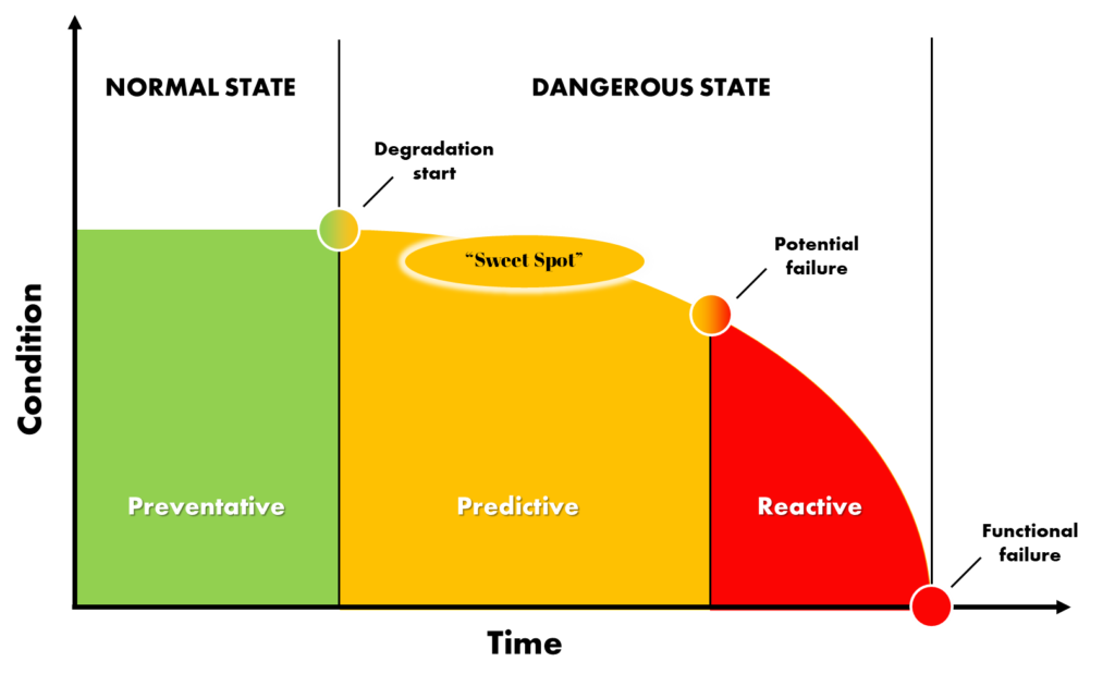
Maintenance Modes, Asset Condition vs Time to Failure
Identifying equipment degradation at the earliest stage beyond the “normal state” is optimal for predictive maintenance. Maintenance professionals can be alerted at the earliest signs of failure by monitoring asset conditions with oil analysis, ultrasound, vibration, and infrared thermography. When equipment failure is predicted to occur, condition-based maintenance can be carried out with repairs made according to the priority of equipment needs. Maintenance and repair costs can be optimized by eliminating rush orders for parts and conducting services during planned outages and turnarounds.
Infrared Thermography Inspection
Infrared Thermography
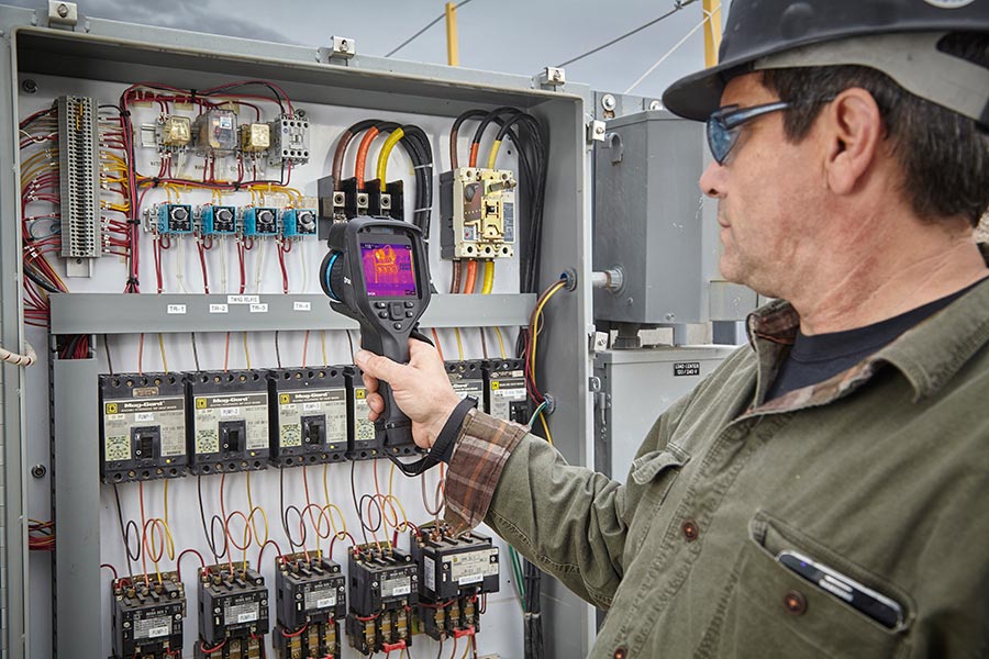
Infrared (IR) cameras operate on the heat transfer principle of radiation. The infrared camera has a focal plane array of detector elements that sense infrared light from object surfaces. The radiation captured by the infrared camera detector is digitized, converted to data, and displayed as a viewable image. Calibrated IR cameras can report temperature measurements from specific spots, lines, and areas on live or recorded images.
Infrared Thermography is a proven and effective way to monitor machine health and detect potential failure points before a failure can occur. Critical in-service health and wear characteristics of electrical, mechanical, hydraulic, and steam equipment can be assessed using thermal imaging, and temperature data is valuable to predictive maintenance programs.
Infrared Thermography is the easiest non-contact temperature measurement method available. Monitoring mechanical components such as motors, bearings, heat exchangers, cooling fans, exhaust vents, pipes, and more for “hot spots” can alert of possible future fail points. In addition, thermal scans of electrical components, such as cables, wiring, terminals, and control panels, can quickly reveal problems such as load imbalance, current overload, loose wires, corroded terminals, or heat management issues. Thermal imaging makes these otherwise invisible problems visible so corrective action can be taken before catastrophic failure. Deploying IR cameras to monitor critical equipment can be a very effective first line of defense against unexpected and unplanned downtime.
Vibration Analysis
Vibration Analysis
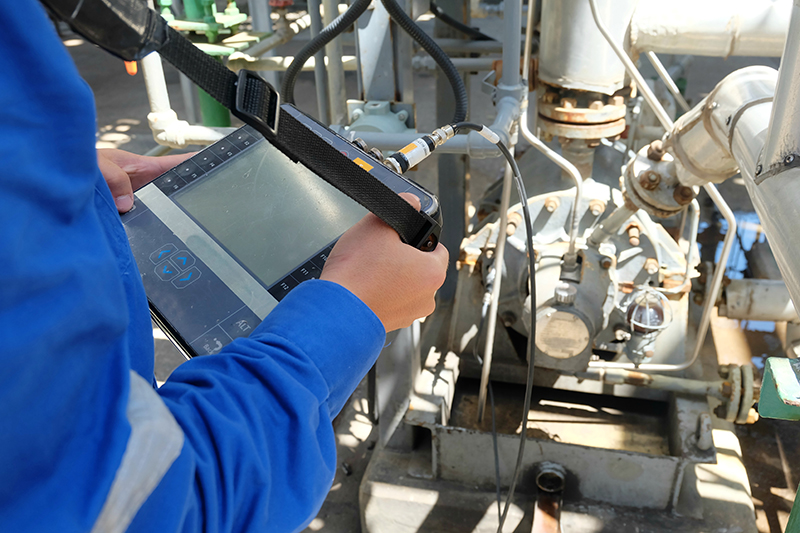
Anytime a piece of machinery is running it is making vibrations. Vibration analysis is a condition monitoring technique for measuring machinery vibration levels and frequencies and then using that information to analyze how healthy the machines and their components are.
A vibration sensor is a device used to assess the amount and frequency of vibration in a mechanical system. The most common vibration sensor is an accelerometer. Accelerometers are mounted directly on the machine for measurement. Signal data from the accelerometer is recorded by connecting a data collector. The recorded signal data is then analyzed by a computer program and trained vibration analysts to determine the machine’s health and identify possible impending problems.
Vibration analysis is an effective evaluation method for detecting mechanical imbalance, misalignment, looseness, and late-stage bearing wear.
Ultrasound Inspection
Ultrasonic Inspection
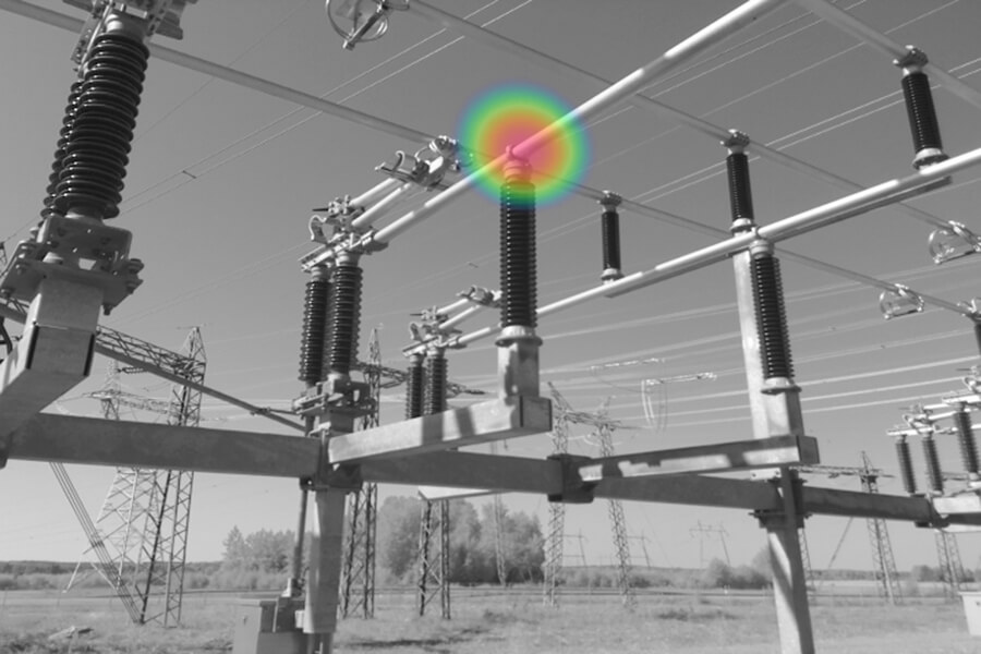
Ultrasonic sensors detect airborne and structure-borne ultrasounds inaudible to the human ear and convert them into audible and viewable signals. Ultrasound is a proven technology that detects specific mechanical, electrical, and other faults much sooner than other technologies. For instance, ultrasound monitoring can detect the most subtle ultrasonic noise from the friction of poorly lubricated or failing bearings before an infrared camera will see the resulting heat. Additional applications for ultrasound inspection include the detection of leaks, blockage, stuck valves, and failed traps in steam systems. Or identifying anomalies like corona, arcing, and tracking in electrical systems.
A recent development in ultrasound inspection is the release of ultrasonic imagers. These imagers collect ultrasonic sound signals and superimpose them on a corresponding visible image of the target area. Ultrasonic imagers simplify the analysis process by creating a visible ultrasound image. Ultrasonic imagers are available in portable hand-help and fixed-mounted configurations.
Oil Analysis
Oil Analysis
Sampling and examining the lubrication oil of a machine can give clues to the machine’s health. For example, understanding particulate matter’s quantity, composition, and size in a machine’s lubricating oil can indicate machine wear. A typical machine will have low levels of solids with a size of less than 10 microns. As the machine components wear, the size and amount of particulate will increase. Oil analysis can also reveal oil health and identify the presence of contaminants that compromise lubrication efficiency.
As the equipment required to conduct oil analysis can be expensive and require extensive operator training, most companies will collect samples on a routine basis and submit them to a lab for analysis. These labs will analyze the samples and provide test reports, helping clients understand if the lubrication oil needs replacement or if a mechanical system should be serviced.
A well-implemented oil analysis program provides a window into lubricated mechanical equipment to help identify and resolve problems early, mitigating unrecoverable downtime.
Other Methods
Other condition-monitoring modalities include motor circuit analysis, radiography, laser interferometry, electrical monitoring, and electromagnetic measurement.


