ASM International is a nonprofit professional society focused on providing scientific, engineering, and technical knowledge to its members and the materials science community. In their education and experimentation labs, they regularly work with innovative inspection solutions that have the potential to improve quality assurance in manufacturing.
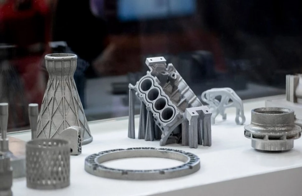
One new application they’re working on is laser powder bed fusion (L-PBF), an additive manufacturing process where a laser is used to weld powdered material to form a 3D object. Think of it like 3D printing, but for metal parts. One of the challenges ASM International is studying is how to assess the quality of the 3D printed parts.
How does laser powder bed fusion work?
The process begins with a bed of metallic powder on a base. A very fine laser selectively heats the powdered material causing it to weld together. By creating thousands (or more, depending on the size of the part) of tiny welds in multiple layers and discarding the unused powder material, users can effectively create a 3D metal object.
The entire process is controlled by a computer, and about 200 parameters need to be properly set up for each part being created. Failure to set these up correctly can lead to challenges during the manufacturing process and poor part quality. For example, if the system isn’t set up correctly, voids or porosities can occur. These can weaken the final part, causing it to fail prematurely.
There are technologies available to evaluate the quality of parts produced by L-PBF. One of the most common is computed tomography, or CT. CT uses X-rays to capture a series of 2D cross-sectional slices of a part. These slices can then be reconstructed into a 3D rendering so that users can view external and internal part features. While effective, using this method alone is time consuming. And in additive manufacturing, speed and efficiency are critical.
Experimenting with Laser Scanning Confocal Microscopy
ASM has an Olympus LEXT™ OLS5000 laser confocal microscope in their lab. The OLS5000 microscope is used in many inspection applications to measure the shape and surface roughness of a sample at the submicron level. Its advantages include speed, ease of use, a long working distance, and precise imaging.

The LEXT OLS5000 microscope in ASM International’s lab.
John Peppler, a senior metallurgist and laboratory manager at ASM International, used the OLS5000 microscope to help speed up the L-PBF process. Specifically, he used the OLS5000 microscope to characterize the weld shape and then compared the results with those from the CT scan.
Evaluating Printed Parts for Defects
The top layer of the printed part shows welds that have been laid down. The shape of the welds and the spaces between them have a lot to do with locating and evaluating potential defects, and analyzing these kinds of shapes is a strength of the OLS5000 microscope.
To set up and complete a full evaluation of a component using a CT scan takes about 3 hours. With the OLS5000 microscope, it takes about 1 hour to scan a 3 mm × 3 mm area to ascertain the surface roughness. In addition, Peppler used the OLS5000 microscope to capture simple line profile measurements of the part—each of these scans took only a couple of minutes.

A color image of the 3 mm × 3 mm scan using captured using a long working distance, 50X objective.

A height map of the same area shown in the image to the left.
Although the OLS5000 data doesn’t show the full internal composition of the part, it was effective at evaluating the peaks and valleys present on the part’s surface. The microscope enables users to define a ‘valley’ as measuring a specific depth below the part’s surface and then display those measurements. The mapping provided by the laser microscope can potentially help improve component quality by checking to ensure the L-PBF system is working correctly. If, for example, there are large voids between the welds on the top layer that are not supposed to be there, it can reasonably be assumed that such gaps likely exist inside the part as well, so the piece’s integrity should be verified by a CT scan.

Images captured by an OLS5000 microscope from three 3 mm × 3 mm scans showing intensity, color, height map, and stage map.
Fine-Tuning the L-PBF System
The rapid linear roughness measurement capabilities of the OLS5000 microscope are potentially helpful to properly tune the system during setup. Each L-PBF machine has a set of parameters that need to be properly set to enable it to produce the best possible parts. Getting those dialed in takes trial and error, so fast testing solutions that can help speed this process are critical.

A series of linear height profiles across L-PBF welds. The valleys between adjacent welds are significantly deeper than the build height layer, indicating a flaw.
Some key factors that need to be measured are the number, location, and depth of any valleys in the part. The microscope’s high resolution and non-contact, laser-based measurement approach accurately measures the depth of even narrow valleys between welds. Peppler hopes that by creating a map of the line scans, he can create a tool that will help manufacturers fine-tune their L-PBF manufacturing machines not just for shape, but also for internal soundness. While the OLS5000 microscope can’t replace CT scanning, it can be a critical component of a process that makes the setup and quality assurance processes more efficient.
Laser powder bed fusion and similar additive manufacturing techniques are rapidly gaining in popularity. The ability to print 3D metal parts with complex shapes and geometries without forging or milling is attractive to many manufacturers. However, as leading-edge manufacturing techniques are developed, they must be supported by advanced inspection technologies. The collaboration between Olympus and ASM International aims to help by combing advanced equipment with skilled educators and researchers who work together to develop solutions to emerging challenges.
Blog By : Kristopher Lee (Manager, Marketing Communications)
Kristopher joined Olympus in 2019 and is based in our Webster, Texas office. He works with our sales and product management teams to grow Olympus’ brand and customer base in North and South America. The product lines he supports include industrial microscopes, analytical instruments, nondestructive testing instruments, and industrial videoscopes.


