A welder's primary concern in work is ensuring his weld is sound. For this reason, it's essential for an inspector examining the weld to be able to spot a variety of weld discontinuities, including:
- Porosity.
- Incomplete fusion.
- Incomplete joint penetration.
- Unacceptable weld profiles.
- Cracking.
The first step toward understanding weld discontinuities is to examine some welding terminology. Discontinuity is defined as an interruption of the typical structure of a material, such as a lack of homogeneity in its mechanical, metallurgical, or physical characteristics. A discontinuity could result from a defect but isn't necessarily a defect.
On the other hand, a defect is a discontinuity that by nature or accumulated effect (for example, total crack length) renders a part or product unable to meet minimum applicable acceptance standards or specifications. A defect results in the rejection of the part or product. Because we're examining these phenomena outside the requirements of specific welding codes or standards and don't discuss their limitations in terms of these documents, we'll use the word discontinuities to describe them. So the first type of weld discontinuity we'll address is porosity.
1. Porosity
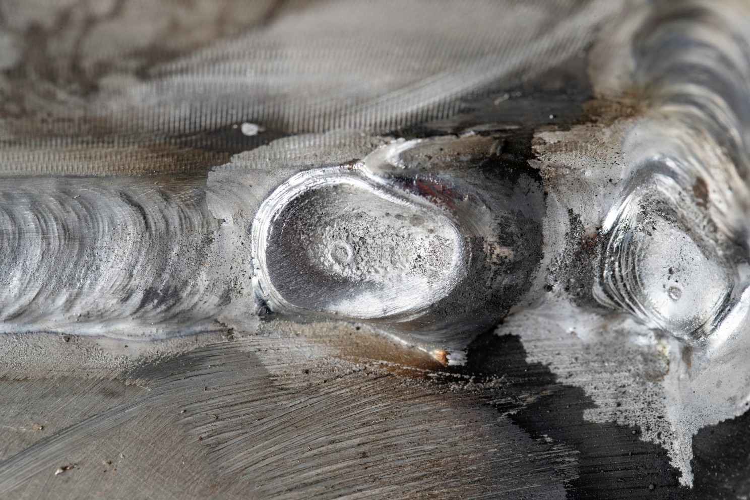
Porosity is defined as a cavity-type discontinuity formed by gas entrapment during solidification. These trapped gases in the molten weld may form bubbles or pockets as the weld solidifies. The four main reasons for the presence of gases that cause porosity are:
- Dirty base material contaminated with hydrocarbons such as oil, grease, or paint.
- Moisture on the joint surface or electrode in water or hydrated oxides or water leaks from poorly maintained cooling systems that can introduce hydrogen into the welding process.
- Insufficient or improper shielding caused by an inadequate shielding gas flow rate; gas that's contaminated from its source or its delivery system; or wind or draft that prevents the gas from adequately protecting the molten weld metal.
- Incorrect welding conditions or techniques.
Porosity often is classified by its shape and distribution within the weld, such as uniformly or randomly scattered, cluster, or linear. Each of these porosity distributions may have different acceptance levels within a welding code or standard. The most practical methods for controlling or eliminating porosity are using clean base materials, properly storing uncontaminated welding consumables, adequately maintaining welding equipment, using proven welding procedures, and welding in acceptable environmental conditions.
2. Incomplete Fusion
Because these terms are sometimes misused, it's essential to understand the difference between these two weld discontinuities. Incomplete fusion is a weld discontinuity in which fusion doesn't occur between the weld metal and fusion faces or adjoining weld beads. This absence of fusion can occur at any location within the weld joint and be present in fillet welds or groove welds.
Incomplete fusion may result when the temperature of the base material or previously deposited weld metal is not elevated to its melting point during the welding process. Incomplete fusion often is found on one leg of a fillet weld and is caused by an incorrect welding angle, which distributes heat nonuniformly between both sides of the joint. It also may be caused by oxides or other foreign material on the surface of the base material.
3. Incomplete Joint Penetration
Incomplete joint penetration is a discontinuity in a groove weld in which the weld metal doesn't extend through the joint thickness. Instead, it's the failure of the filler metal or base metal to fill the root of the weld.
Some common causes of incomplete joint penetration are a bad groove weld design or a fit-up that is unsuitable for the welding conditions. For example, incomplete joint penetration can occur if the root face dimensions are too large, the root opening is too small, or the included angle of a V-groove weld is too narrow. These joint design problems restrict the weld's ability to penetrate the joint's thickness. Incomplete joint penetration can be prevented with the correct joint design and fit-up per welding procedure requirements.
Understanding these weld discontinuities will help welding inspectors identify them and, more important, prevent them from occurring in production. Using welding inspection as a preventive tool within the quality system is more efficient than only as an appraisal technique to sort bad welds from good welds.
4. Unacceptable Weld Profiles
The profile of a completed weld may have a considerable effect on the performance of that weld in service. Therefore, welding inspectors must identify discontinuities through visual inspection and evaluate their acceptance or rejection according to the applicable welding code or standard acceptance criteria.
Unacceptable weld profiles can cause a reduction in base material thickness, reduction in weld size, or stress concentrations on the weld or plate surface. These types of weld discontinuities often seriously detract from the overall performance of a welded component in service.
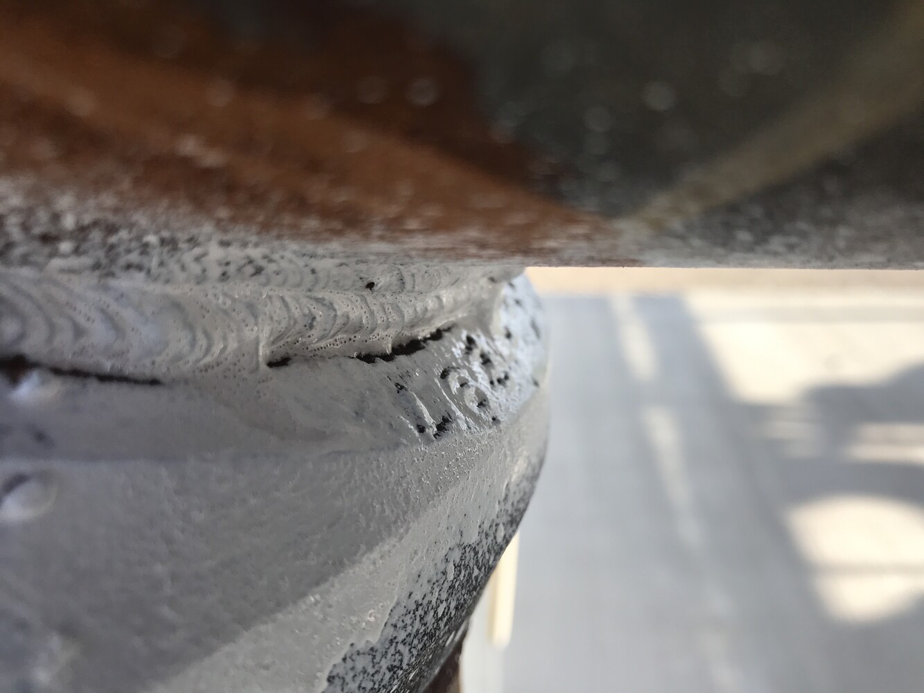
Some weld profile discontinuities are undercut, overlap, insufficient throat, and excessive convexity. The undercut is defined as a groove that is melted into the base metal adjacent to the weld toe or weld root and left unfilled by weld metal.
The term undercut describes two specific conditions. The first is the melting away of the base material at the sidewall of a groove weld at the edge of a bead, which produces a sharp recess in the sidewall in the area where the next bead is to be deposited. This type of undercut can entrap inclusions within the cavity, which a subsequent weld bead may cover.
This condition can usually be corrected by grinding down the recess before depositing the next bead. However, if the undercut is slight, an experienced welder who knows how deep the arc will penetrate may not need to remove it. Likewise, the undercut of the sidewall of a groove weld won't affect the completed weld if the condition is corrected before the next bead is deposited.
The second condition is the reduction of the base metal's thickness at the line where the weld bead on the final layer of weld metal ties into the surface of the base metal. This position is known as the toe of the weld. This condition can occur on a fillet weld or a butt joint.
The amount of undercut permitted at the completed weld's surface is usually specified within the welding code or standard being used. However, the maximum permissible undercut requirements for completed welds should be followed stringently because excessive undercut can seriously affect the performance of a weld, particularly if it's subjected to fatigue loading in service.
Both undercut types are usually caused by an incorrect welding technique, incorrect electrode positioning, or incorrect travel speed. High currents and a long arc increase the probability of undercut.
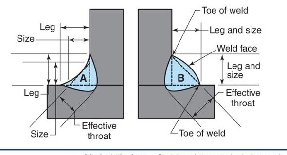
Overlap. Overlap is defined as a protrusion of weld metal beyond the weld toe or weld root. This condition occurs in fillet welds and butt joints and produces notches at the toe of the weld that is undesirable because of their resultant stress concentration under load. This discontinuity can be caused by incorrect welding techniques or insufficient current.
Insufficient Throat. Insufficient throat usually occurs in fillet weld and butt joint profiles that are concave. Excess concavity reduces throat thickness, which considerably reduces weld strength. This condition usually is caused by excessive welding current or arc lengths.
Excessive Convexity. Excessive convexity can produce a notch effect in the welded area and, consequently, the stress concentration under load. For this reason, some codes and standards specify the maximum permissible convexity of a weld profile. Insufficient current or incorrect welding techniques typically cause this condition.
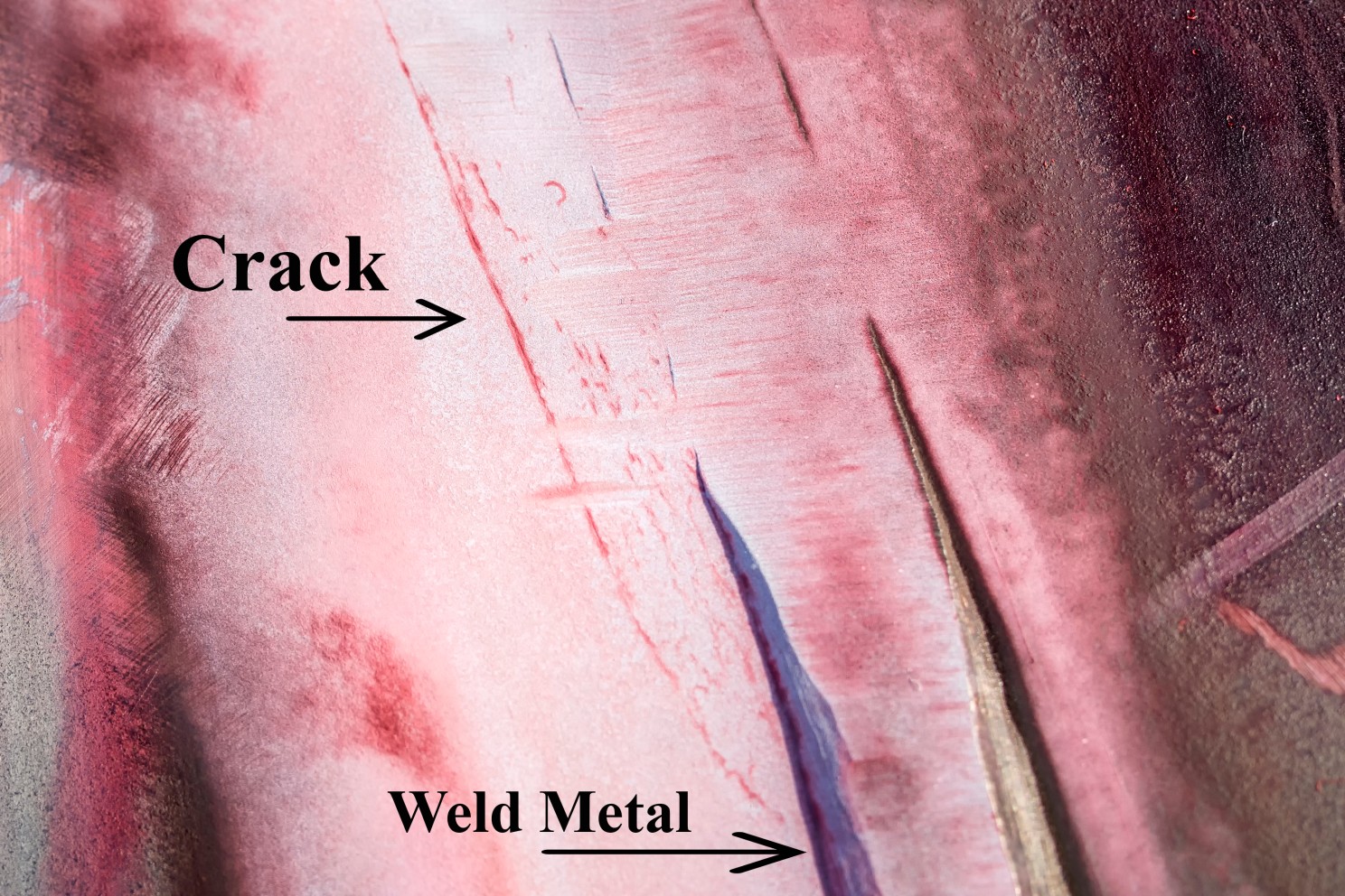
Cracking
Cracks in a weldment are probably the most dreaded weld discontinuities. Cracking is a complex subject because so many materials and applications are used in welding.
The base material's crack sensitivity may be associated with its chemistry and susceptibility to the formation of elements that reduce its ductility. Excessive stresses in the weld joint, mainly if the material is in a crack-sensitive condition, can cause cracking to occur.
The welding operation can produce stresses in and around the weld, introducing extreme localized heating, expansion, and contraction.
Cracking often is caused by stress concentration near discontinuities in welds and base metal and near mechanical notches in the weldment design. In addition, hydrogen embrittlement, which causes a loss of elasticity and exists in weld metal because of hydrogen absorption, can contribute to crack formation in some materials.
Hot and Cold Cracks. Cracks are classified as one of two types: hot or cold.
Hot cracks develop at elevated temperatures, propagate between the grains of material, and commonly form during the solidification of weld metal.
Cold cracks develop after solidification of the weld due to stresses and propagate both between grains and through grains. Cold cracks in steel sometimes are called delayed cracks and often are associated with hydrogen embrittlement.
Hot and cold cracks can be categorized further as base material cracks and weld metal cracks.
Base Material Cracks. The heat-affected zone (HAZ) cracking most often occurs with base material that can be hardened. High hardness and low ductility in a HAZ often result from a metallurgical response to thermal welding cycles. For example, in ferritic steels, hardness increases, and the ductility decreases with an increase in carbon content and a faster cooling rate.
The HAZ hardness depends on the base material's ability to be hardened, which in turn depends on the base material's chemical composition. Carbon has a predominant effect on steel's hardenability. For instance, cast iron contains between 2 and 4.5 percent carbon, giving high alloy hardness and low ductility. Welding this material without seriously considering cooling rates and residual stress invariably will result in base material cracking.
Weld Metal Cracks. Weld metal cracks can be divided into three types:
- Transverse, which are perpendicular to the direction of the weld.
- Longitudinal, which travels in the same direction as the weld, is often confined to the weld's center. This type of crack may be an extension of a crack initially initiated at the end of a weld.
- Crater is an abrupt weld termination, if a crater is left unfilled with weld metal. These cracks usually are star-shaped and initially extend only to the edge of the crater. However, they can propagate into longitudinal weld cracks.
Dealing With Cracks. Cracks are unacceptable discontinuities and are detrimental to weld performance. A crack, by its nature, is sharp at its extremities, so it acts as a stress concentration. The stress concentration effect is greater than that of most other discontinuities.
Cracks tend to propagate, contributing to weld failure under stress. However, cracks aren't permitted in weldments governed by most fabrication codes regardless of their size. Instead, they must be removed by grinding or gouging, and the excavation filled with sound weld metal.
Successful welding procedures incorporate the necessary controls to overcome the tendency for crack formation. Such controls are preheating temperature, interpass temperature, consumable type and preparation, and post-weld heat treatment.
Welding inspectors are responsible for evaluating these procedural controls during inspections to ensure welding is performed to minimize the possibility of weld cracking.
Detecting and Evaluating Discontinuities
Weld discontinuities often are detected through visual inspection. However, some are detected with inspection methods, such as radiography, ultrasonics, liquid penetrant, and magnetic particle inspection.
The maximum acceptable limitations for these discontinuities depend on the performance requirements of the welded component and are specified in the appropriate welding code, standard, or specification. The welding inspector is often required to determine the extent of discontinuities and establish their acceptance or rejection based on the relevant acceptance criteria.