1. Introduction
Flexible risers are used in the offshore oil and gas industry to connect wells with floating platforms in deep sea environments. Being flexible, high-pressure pipelines, this implies that they endure considerable cyclic loading and tensional stresses. Their design has matured over the last years, but integrity management is still a demanding task. They have a complex structure made of different layers of polymer and steel materials, each layer being responsible for a specific loading or sealing purpose. The layers are not bonded to each other, hence summarized under the term unbonded flexible riser [1]. The schematic of a flexible riser is shown in Figure 1.

Figure 1: Schematic of a flexible riser structure. Taken from [2]
The threats to the integrity of this pipe type are manifold. One of the common failure modes is the degradation of the armour wire layers. This can be initiated by water flooding of the annulus between the external sheath and the pressure sheath. If Annulus Flooding is present can be detected by the FADS technique. Once water is present in the annulus, an electrolyte may form, which is one of the preconditions for corrosion to take place in the steel components. Some of the integrity assessment methods thus focus on the detection of flooding in the annulus [3]. In aparticular scenario, CO2 permeating through the pressure sheath from the medium can form suitable conditions for stress corrosion cracking. This has been described in [4].
Rigid pipelines are typically inspected from the inside by the use of either ILI tools or by umbilical or tethered tools. This is difficult with flexible risers. The innermost layer is a carcass usually made of a stainless-steel material. The next layer from the inside is a polymeric pressure sheath. Electromagnetic methods of non-destructive testing would struggle to receive information from the steel components through these layers. The same is true for ultrasonic-based methods that suffer from the changes in acoustic impedance of the different materials. An internal inspection method for the more outer components is thus not possible. However, as risers these pipes are easily accessible from the outside. For flowlines a full circumference external inspection would require a dredging for the permissible free span length.
2. Inspection Tool
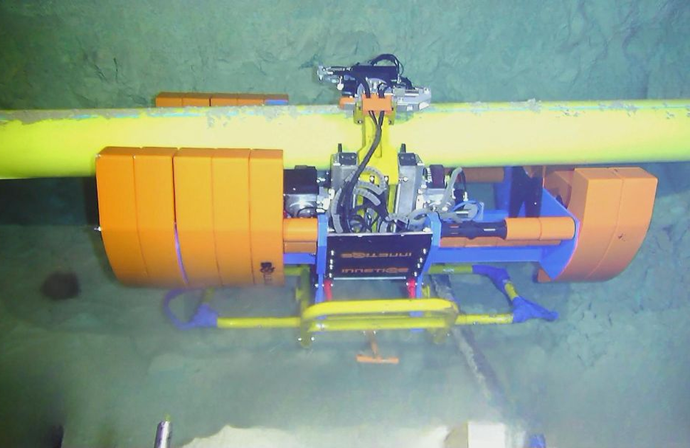
An inspection crawler has been developed at InnetiQs which can be equipped with different inspection technologies tailored to different inspection tasks. The crawler is deployed by an ROV and attaches itself by means of hydraulically actuated arms. Once affixed to the pipe it crawls along the pipe and around its circumference to reach every spot on the surface. A cleaning of the surface is usually not required as marine growth in deeper waters is minor. The tool stays attached to the ROV with an umbilical. It uses the ROVs communication means to submit the inspection data to the top-site control usually in a supply boat. Cameras mounted on the tool allow for a close visual inspection (CVI) in parallel.
The available inspection technologies comprise the Subsea Crawler FADS for flooded annulus detection. The MagControl FR allows for the inspection of deeper layers beyond the surface of the outer layer for ruptures or corrosion. The IncoScan is used to inspect insulated riser, i.e. outer sheath thickness of up to 75 mm, for wire ruptures. Finally, the HiREC technology inspects the outer layer for cracking. An image of the scanning tool clamped onto a riser is shown in Figure 2.
The available inspection technologies include:
- FADS – for flooded annulus detection
- MagControl FR – for inspection of deeper layers beyond the outer surface, detecting ruptures or corrosion
- Incoscan – for insulated risers with outer sheath thickness up to 75 mm, detecting wire ruptures
- The new HiREC – for high-resolution crack detection in the outer layers (An image of the tool clamped onto a riser is shown in Figure 2.)

Figure 2: Subsea Crawler attached to riser
3. Inspection technology
Except for the FADS tool the inspection techniques are based on eddy current technology (ECT). The advantage of ECT is its ability to measure over a distance. ECT is based on the impedance measurement of a coil depending on the induction of eddy currents in the metallic components of the flexible riser. Electromagnetic induction is easily possible over a distance if the components between sensor and specimen are nonconductive and nonmagnetic. The typical sheath thickness of deep-water flexible riser varies between 8 and 22 mm for non-insulated pipes. In order to measure over such a distance, the sensors are designed for the specific purpose. They are naturally larger and more complex than standard absolute type surface probes. The special structure of the flexible pipe to be inspected should also be known prior to the inspection as the sensor arrangement will be adopted to the structure. Furthermore, the sensors have to be produced to work in an environment of 250 bar outer pressure. This requires proper potting and ample upfront pressure testing before commissioning the sensors.
4. Method verification
The technology has been verified in various manners. In a first step the sensor arrangement was tested by scanning over artificial defects produced into original armour wires. The XY-table used is shown on the left of Figure 3. The wire arrangement with artificial defects in the middle of the figure and the obtained signals on the right.

Figure 3: Artificial defects for the verification of the method. Right: Scan results
The defects were produced with EDM (Electrical Discharge Machining) because any type of milling may distort the electromagnetic properties of the steel material. For eddy current testing this may alter the signal. The cracks are the four indications on the left in Figure 3. On the right metal loss indications have been added for comparison. The data shown on the right is untreated raw amplitude. The large signal on the top and the bottom correspond to the start and end of the wire assembly. The data was recorded with a sensor lift-off of 20 mm. Subsequent tests consisted of scanning over artificial defects in a cylindrical test sample and the scanning of a flexible riser pipe section retrieved from offshore operations.
5. Scanning process
The scanner movements are automated such that the scanning and repositioning is done by a hydraulic valve control. For risers the full length can be scanned except for the connectors or possible buoyancy modules. The full length is divided into smaller scan sections. The scanner runs axially along the riser for the length of the section. It is usually chosen to be between 5 and 10 m. The scanner is then rotated around the pipe by an angle predetermined by its outer diameter. It runs back and forth until the full circumference is scanned. The reason for limiting the axial scan distance is to ensure that the circumferential positioning is reproducible. The scanning is typically performed at a speed of 50 m/h by adding scan section to scan section. For the scanning in excavated spots the scan section is naturally much shorter. The distance of the scanned length is recorded by a distance encoder. This allows for an exact mapping of the scanned surface.
6. Typical results
As the measurement principle is based on eddy current technology the results are depicted as C-Scans in which the signal amplitude is depicted over the scanned surface. Many different images can be compiled depending on what detail needs to be enhanced. The postprocessing of the data include amongst others filtering, phase sensitive selection and background subtraction. The selection of the postprocessing parameters allow for the classification of the obtained signals. As pointed out before the technology is sensitive to different kinds of defect types. For example, the HiREC version would detect cracks, corrosion and wire distortions. The selection of the postprocessing parameters will distinguish between these different signal types. The detailed analysis is done using the depiction of the signal in the impedance plane.
Another method of processing is the use of multi-frequency eddy current. The scanning is done with two (or more) frequencies at once. Different types of defects react to different frequencies in a distinct manner. Respective mixing of the signals of the two frequencies allows for enhancing or masking of specific signal types. An example is shown in Figure 4. The upper two images show the signals obtained on a retrieved sample of a flexible riser. They are measured with different eddy current frequencies. The lower two images show the same data with different mixing parameters. The upper of them shows an enhancement or metal loss like features. Note, that there is a structure running along the overlap line of the anti-wear tape. It is assumed that defects in flooded annuli often start at this point, as apparently conditions for corrosion are ideal here. The lowest image shows the crack-like features. A cut wire shows up in both images.

Figure 4: Data from a sample retrieved from offshore service
7. Conclusion
The newly developed technology offers a novel approach towards flexible riser integrity. Whereas flexible risers used to be exchanged when they reach their calculated end-of-life it now becomes possible to determine the need to change out the riser based on inspection results. The tool has been used in an offshore environment to a water depth of up to 2300 m. It may also become reasonable to carry out a base-line survey. When flexible risers are exchanged the installationprocess may cause problems when overbending or overstretching the risers. To record the status after the installation is reasonable and pure general visual inspection is unlikely to reveal the true condition of the riser.
8. References
- Specification for Unbonded Flexible Pipe, vol. API 17J. 2014.
- S. Péronne, C. Izarn, P. Estrier, O. Caro, J.-M. Leroy, and D. Charliac, ‘Flexible Pipe Hysteretic Bending Behavior: Comparison With Experimental Characterization and Finite Element Method’, in Volume 5A: Pipeline and Riser Technology, St. John’s, Newfoundland, Canada: American Society of Mechanical Engineers, May 2015, p. V05AT04A032. doi:10.1115/OMAE2015-41281.
- A. Assis, A. Boenisch, C. Boynard, G. Vale, and K. Reber, ‘Development of NDT Inspection Tool for Subsea Non-Insulated Flexible Pipes to Support SCC-CO2 Integrity Management for Brazilian Deep Offshore Application’, presented at the Offshore Technology Conference, May 2025, p. D031S032R005.doi: 10.4043/35941-MS.
- C. Vasconcelos Ferreira Lobo and M. L. Ribeiro, ‘SCC-CO2 Failure Mode: Literature Review and Available Technologies Used to Inspect and Access the Integrity of the Flexible Pipes’, presented at the Offshore Technology Conference, May 2023, p. D041S056R001. doi:10.4043/32252-MS.
Authors: Andreas Boenisch & Dr. Konrad Reber


