ABSTRACT
The rapid progress in the construction of heavy-haul and high-speed railways has led to a surge in rail defects and unforeseen failures. Addressing this issue necessitates the implementation of more sophisticated rail inspection methods, specifically involving real-time, precise detection, and assessment of rail defects. Current applications fail to address the evolving requirements, prompting the need for advancements. This paper provides a summary of various types of rail defects and outlines both traditional and innovative non-destructive inspection techniques, examining their fundamental features, benefits, drawbacks, and practical suitability for railway track inspection. It also explores potential enhancements to equipment and software. The comprehensive review draws upon pertinent international research and review papers. Furthermore, the paper introduces a fusion of inspection methods aimed at enhancing the overall reliability of defect detection.
1. Introduction
There has been a rapid increase in train density in recent years, load capacity, and running speed within railway transportation, particularly in high-speed railway transportation [1]. The significance of railway transportation in the modern transportation system has grown considerably. Consequently, there is an escalating concern for rail safety [2]. Rails endure substantial mechanical loads and challenging environmental conditions as a routine part of their operation. The wheels’ weight is the main source of mechanical stresses, which puts rolling contact pressure and shear and bending pressures on the rails [3]. Additionally, rails are consistently exposed to natural elements, resulting in phenomena such as corrosion and thermal stress. Notably, thermal expansion has a substantial impact on ideal and flawless rails used in high-speed railways, influencing the concentration of internal stress within the rail structure [4]. Rail defects are primarily found in various sections of the rail, including the rail’s head, its web, foot, and specific areas. The stress concentration is notably pronounced on the rail’s head [5]. Thus, common Rolling Contact Fatigue (RCF) flaws include cracks, stripping, corrosion, wear, crushing, shelling, and internal damage, all of which are mostly visible on the outside and within the rail-head. Significant defects including cracks, severe corrosion, and bolt-hole fatigue, can occur in the rail-web. The two main defects found in the rail foot are cracks and rust. Moreover, the complexity of defect types increases on other rail parts, such as welding joints and turnouts [6].
The rail, a crucial component of the railway track, is vitally important for ensuring the safety of train operations and passenger comfort. Consequently, it becomes imperative to conduct timely inspections of the rail using diverse devices employing Non-Destructive Testing (NDT) methods [7].
Conventional inspection methods for railway track inspection are not only time-consuming and labor intensive but are also susceptible to various factors like challenging environmental conditions and inspector experience. In contrast, NDT facilitates rapid detection of rail defects, offering standar
dized and efficient inspections that minimally disrupt regular operations [8].
Search, identification, and evaluation are the three main processes in the typical NDT rail defect detection method. An array of NDT techniques is used in the search phase to cover every facet of the rail, including the internal components, foot, head, surface, and subsurface. The process of identification involves computing outcomes using quantitative traits obtained from NDT data. Lastly, evaluation includes determining the extent of rail flaws and classifying them according to predetermined standards and indicators [9].
With an increasing demand for comprehensive, rapid, and accurate rail defect detection, and to provide valid and scientific information, testing methodologies must be evaluated against current field applications before this goal can be accomplished.
This paper provides a summary of rapid rail defect detection technologies, examining the advantages and limitations of different NDT methods. The benefits of combining the various NDT techniques are then integrated to create a comprehensive detection guideline.
Rail defects can be categorized according to their location as either internal defects (caused due to rail manufacturing defects or during the service), or surface defects (caused by rail wear and fatigue). Though different countries may adhere to their classification standards, the common type of defects generally remain consistent across regions.
Internal defects originate within the rail, encompassing transverse defects, rail bottom cracks, bolt hole cracks, longitudinal defects, and other variations (Fig. 1). These defects progress discreetly and pose a significant risk of causing hazardous derailments.
Surface defects, in contrast, manifest on or just beneath the rail’s surface and encompass issues like squats, shelling, head checking, rail indentations, wheel burns, and other anomalies (Fig. 2). The majority of head checking defects are categorized as RCF cracks, a kind of surface defects that is extremely dangerous. These surface irregularities have the potential to disrupt ultrasonic rail flaw detection, leading to the possibility of the rail failing to identify internal defects [9].

Fig. 1. Internal defects in rail: (a) transverse defects, (b) bolt hole cracks, and (c) longitudinal defects.
2. Non-destructive testing methods for railway track defects detection
NDT methods employed for detecting rail defects, can be divided into two primary categories: Visual Testing (VT) and physical inspection. VT relies on various image processing techniques to segment and identify rail images, thereby extracting sufficient defect-related information. Conversely, physical inspection utilizes a variety of physical signal processing techniques to examine the rail. This section will elaborate on each category, outlining its types and primary characteristics.

Fig. 2. Rail surface defects: (a) spalls and gauge corner checking, (b) shelling, (c) squats, and (d) wheel burn defect.
2.1. Visual testing method
The visual inspection technique represents a non-contact method extensively employed in NDT due to its rapidity and precision [10]. In the context of railway track fault detection, visual inspection relies on utilizing a high-speed camera that has the capability to capture high-quality images of the rail and its components, particularly its surface, while the train traverses the track. Subsequently, the captured image data is transmitted to a computer through a data acquisition device. Following this, specialized software processes that image data to as certain the appearance of any defects on the rail. Visual inspection is adept at identifying surface irregularities such as corrosion, cracks, deformations, wheel burn, etc., on the rail. The basic principle of VT is depicted in Fig. 3.
From Fig. 3, it is evident that the visual system initially extracts the image of the rail surface. Subsequently, the image is converted to grayscale to facilitate the detection of defects with high contrast.
Automated visual inspection systems are crucial when it comes to tracking elements such as rail head profile, surface damage, missing bolts, pincers position, rail gap, moving sleepers, base plate condition without ballast, lack of ballast, and wear percentage, automated visual inspection systems are essential. A variety of inspection types and needed resolution quality can affect the testing/inspection speed, which can range from 1 to 320 km/h [11].
VT of rails can be inaccurate for a number of reasons. First, because of blurring effects due to camera movement, high quality movies or pictures are needed to provide data that is reliable for analysis [12]. Secondly, conventional cameras lack the capability to capture image data about the depth. Thirdly, changes in environmental light throughout the day significantly affect the captured image data, impacting the defect detection stability. To address these issues, several research have been carried out.
Color line scan cameras and spectral image differencing techniques have shown promise in identifying rail surface flaws, which resolves the first problem. Cameras with powerful scanning functions and excellent image clarity, such as Charge-Coupled Device (CCD) cameras, are utilized for visual inspection, offering a high signal-to-noise ratio and high sensitivity in captured images. A/D converters, data storage units, timing generators, and other control logic are used in the acquisition of pictures using linear CCD image sensors [13]. Following the digital signal conversion of the images, the rail surface fault identification process is carried out. 120 km/h is the validated speed of non-contact and dynamic rail fault inspection systems using fast line matrix CCD camera technology [14]. For real-time detection, data analysis and inspection speed must be balanced. To determine the sections of the railway track that are problematic, offline data analysis can be carried out if real-time evaluation is not feasible [15]. Notable rail inspection vehicles, such as the VIS integrated rail inspection system by ENSCO and the Rail Check created by Alias Elektronik in Germany, use cutting edge camera technology to automatically identify faults in the rail system [16].
3D vision technologies, such as 3D structured light technology and binocular stereo vision, have been gradually used to address the second issue. Using two images of the rail to be measured taken from various angles, Binocular Stereo Vision uses the parallax principle to derive the object’s 3D geometric information by calculating the position variation between matching spots in the images. In order to get 3D information of modulated images through visual modeling and image processing, the 3D structured light camera illuminates a structured light illumination pattern onto the target object [17].
As for the third problem, the camera can scan the rail surface under linear laser illumination, thus integrating machine vision with 3D linear laser inspection technology helps partially offset the impacts of light changes [18]. In locations where light changes, algorithmic processing of picture data can further increase the accuracy of visual inspection for rail concerns. Various image processing techniques, including quantification, feature extraction, defect categorization, and pre-processing, are used in the procedure. Pre-processing typically includes grayscale adjustments, image enhancement, and image segmentation. Rail extraction strategies remove sub-images, which enables the local nor malization procedure to improve the contrast of the rail image [19]. The algorithm’s fine extractor distinguishes between actual faults and noise spots from anomalies acquired by pre-processing the image data. The coarse extractor uses this information to find flaws in the rail surface image. Feature extraction involves characterizing defects using algorithms such as Local Binary Pattern, Directional Chain Codes, and Histogram of Oriented Gradient [20]. Rail fault inspection has been subjected to several algorithms, including as K-means and decision trees, in order to improve classification accuracy. Due to the system’s capacity to interpret images quickly, flaws may be quantified using the learning-from examples approach [21]. As a type of supervised learning, deep learning detection techniques efficiently recognize fresh picture samples by gaining knowledge from large amounts of image data. They exhibit better generalization and robustness compared to traditional methods [22].
In summary, VT method of rails demonstrates high speed and accuracy. However, it has limitations as it is not capable of detecting microcracks and internal defects. Therefore, it cannot replace ultrasonic inspection.

Fig. 3. Visual testing of railway track.
2.2. Ultrasonic testing method
Currently, Ultrasonic Testing (UT) technology for rail defects is in constant development and improvement, featuring numerous applications in this field [23]. An ultrasonic transducer, pulser/receiver, and display unit are the standard components of the UT system, as shown in Fig. 4. In order to drive the transducer and produce high-frequency ultrasonic energy, the pulser/receiver functions as an electronic device that generates high voltage electrical pulses. The most often utilized ultrasonic frequency range for rail fault detection is 0.2–25 MHz, with a range of 0.5–10 MHz. When this acoustic energy is added to the substance, it passes through it as a wave. A portion of the energy reflects back to the transducer from the material’s surface if there are flaws present along the wave path. The electrical signal produced by the transducer from the reflected wave signal is shown on a screen for study [24].
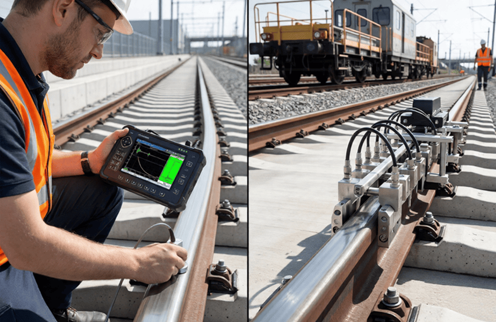
The traditional UT approach for detecting rail defects relies on the ultrasonic pulse-echo technique, primarily designed for identifying internal defects existing within the rail structure. This method finds widespread application in various UT equipment’s, including rail testing vehicles, dual-rail ultrasonic flaw detectors, and walking sticks.
For instance, the Ultrasonic Flaw Detector (USFD) double rail tester, as illustrated in Fig. 5, conforms to the Research Designs & Standards Organization specifications (M&C/NDT/130 & 128) set by the Ministry of Railways through the Railway Board of India [25]. This USFD operates autonomously with a defect display that is divided into two sections: the top half for the RH Rail, and the bottom half for the LH Rail on the screen. The trolley ensures smooth and balanced movement on the track, incorporating automatic gauge tracking. It features two metallic water tanks, each with a capacity of 20 L. Despite its light weight yet robust design, the overall weight, excluding water but including the battery, is approximately 65 kg. It utilizes 18 pulse-echo probes positioned at desired angles, with every probe corresponding to a specific rail defect. Information from the 18 channels is differentiated by the B-scan image’s relative position and color. This principle is applicable to rail defect detection vehicles and walking sticks as well.
Rail inspection can be done either by manual ultrasonic inspection or by a specialized test vehicle. Nevertheless, conventional UT faces various limitations. Firstly, its speed is restricted, and long-distance detection is impractical as the coupling agent is required to fill the gap between the measured surface and the probe. Experimentally verified inspection speeds with conventional ultrasonic NDT range only from 40 to 80 km/h, with real-world speeds potentially of 15 km/h, especially during manual verification of the vehicle [26]. Secondly, the rail defects detection with intricate or irregular shapes poses a challenge due to the constraints of ultrasound inspection systems with conventional multi-probe. The third issue is that the defects on the rail’s top surface and sub-surface due to fatigue damage are challenging to precisely detect and assess. Fatigue cracks on the upper surface impede the incident ultrasonic wave’s ability to penetrate the measured components, which has an adverse effect on the identification of interior flaws hidden underneath the crack. Longitudinal defects reflect ultrasonic waves, which hinder the sound beam’s incidence and make dangerous defects hidden underneath them difficult to detect, especially when the defect is close to the horizontal gauge angle [27].
In response to the limitations of conventional ultrasonic NDT methods, various innovative techniques have emerged, including laser ultrasound technology, electromagnetic ultrasound technology, ultra sonic guided-wave inspection technology, and ultrasonic phased-array inspection.
Multiple arrays of independent piezoelectric wafers are utilized inthe ultrasonic phased-array inspection. Controlling the position and direction of the spotlight through specific rules and timing sequences enables the effective detection of internally complex-shaped defects with high accuracy. Automated ultrasound systems with phased-array probes are replacing the conventional multi-probe ultrasonic inspection systems that can perform numerous tasks, enhancing the speed and accuracy of detection. Particularly in specific areas like welds, ultrasonic phased-array inspection has demonstrated superior efficiency compared to traditional ultrasonic inspection methods [28].

Fig. 4. Basic principle of UT.

Fig. 5. (a) Paras double rail tester and (b) roller search unit probe arrangement.
Guided waves, a variant of long-range ultrasonics, demonstrate effectiveness within distances of up to 30 m by utilizing the reflection or transmission of ultrasound waves across semi-infinite or two semi-elastic media surfaces. When encountering boundaries such as steel rails, different waveforms propagate at their inherent speeds, resulting in the generation of ultrasound-guided waves. Ultrasonic guided-wave inspection technology capitalizes on low-frequency ultrasonic waves, offering advantages such as extended propagation distances and rapid speed. The G-Scan rail ultrasound-guided wave inspection device developed by British Rail Network Rail employs low-frequency ultra sound-guided waves to detect defects in aluminum thermal welds across expansive distances. Despite potential signal attenuation influenced by various factors, the selection of wave frequency and mode significantly impacts the effectiveness of the inspection range.
Electromagnetic ultrasound technology generates high-frequency currents through a zigzag coil, inducing eddy currents on the rail’s head surface. The resulting high static magnetic field causes vibrations, producing electromagnetic ultrasound surface waves.
The utilization of magnetostriction effects and Lorentz force is employed to stimulate and detect ultrasound waves within conductive specimens. Electromagnetic ultrasound technology presents several advantages over traditional ultrasonic NDT methods, including enhanced accuracy, elimination of the need for coupling agents, non-contact measurement capability, and rapid inspection speeds. Developed electromagnetic ultrasound NDT vehicles, like VIGOR Russia’s UD-EMA-RWT-01M and Tektrend’s RailPro, provide comprehensive rail defect coverage at varying speeds.
In laser ultrasonic inspection systems, ultrasound is generated using a pulsed laser in the sample, creating ultrasonic waves by using a thermoelastic process or ablation. Various ultrasonic waves can be produced by pulsed lasers, and surface displacement resulting from ultrasonic waves can be measured with the help of an adaptive interferometer-based laser ultrasonic receiver [28]. Laser ultrasound technology requires no coupling agent, enabling high-speed testing. It is applicable to real-time detection of micro-cracks in rails with high accuracy in harsh environments. Automated laser ultrasonic systems for rapid rail defect detection are capable of identifying surface defects on the rail, along with horizontal and vertical defects within the rail head, even at speeds reaching up to 40 km/h.
In summary, these advanced ultrasonic inspection techniques address the limitations of conventional methods, offering improved accuracy, coverage, and efficiency in detecting rail defects. However, despite their capabilities in detecting deep breakage of rail head surface and internal defects, high-speed systems may struggle with defects lesser than 4 mm deep. Surface defects, especially in the rail foot, corrosion, and alumino-thermic welds, may pose challenges for ultrasonic inspection, requiring ongoing refinement for comprehensive rail inspection.

Fig. 6. Basic principle of ECT.
2.3. Eddy current testing method
Eddy Current Testing (ECT) relies on electromagnetic principles to detect imperfections in conductive materials. Illustrated in Fig. 6, the conventional ECT method involves passing Alternating Current (AC) through a wire coil, creating an oscillating magnetic field, known as the primary magnetic field. Following the principle of electromagnetic induction, the specimen induces eddy currents, generating its own magnetic field, referred to as the secondary magnetic field. This secondary field opposes the primary one, with the effect measurable by assessing the impedance between the coil and the specimen. Any flaws disrupt the distribution of eddy currents, causing impedance changes [29]. Currently, ECT stands as a prominent technique for identifying surface and subsurface defects in railway components, with numerous portable devices employing ECT principles widely deployed in the field [30].
Nevertheless, ECT exhibits a collective skin effect, limiting its capability to detect only the surface and sub-surface conditions of conductive materials. Additionally, a significant challenge with ECT lies in its susceptibility to variations in lift-off. Therefore, it is crucial to maintain a fixed distance (typically within the range of 2 mm) between the measured rail surface and the detection probe [31]. Consistent positioning of the probe at a constant distance from the rail surface is essential during inspections, and any potential lift-off variations must be taken into account, as changes in this variable could impact the accuracy of predicted depth. Hybrid ECT probe for railroad inspection, designed to reduce lift-off noise and enhance crack detection sensitivity. By integrating Transmit and Differential Receiver (Tx-dRx) coils, the probe achieves an SNR above 100 for 1 mm defects, with optimal performance at 0.3 MHz and 1 mm lift-off distance. Experimental and simulation results align, demonstrating improved efficiency in railroad crack detection and safety [32].
Pulsed Eddy Current (PEC), which increases the level of penetration of eddy currents, has been generated in order to overcome these limitations. In order to generate transient eddy currents inside the component under examination, PEC uses a pulsed excitation signal [33]. By measuring the frequency change of the transient currents, the coil creates a voltage that changes over time. This voltage is then examined to uncover anomalies at various depths, describe characteristics, and assess the specimen’s state. This method has the advantages of contactless detection, quick detection speed, and a wide spectrum of content for identifying and differentiating flaws at different depths. New castle University, UK pioneered the application of PEC in rail defect testing, yielding positive results [34].
Moreover, PEC may be used with thermal imaging technologies that rely on the Joule heat and eddy current phenomena of electromagnetism. In order to record the conduction of conductive specimens’ temperature distribution during PEC stimulation, Eddy Current Pulsed Thermography (ECPT) uses infrared thermography. Thermographic data can be influenced by parameters like the depth, inclination, breadth, and length of rail faults. ECPT combines the strengths of PEC and infrared thermography, enabling the rapid visualization of rail fatigue cracks and concentrating heat on the defects. As a result, there is a greater temperature differential between the defective and non-defective regions, which improves the spatiotemporal properties and offers rich transitory information. For minor flaws like micro-defect damage on the rail surface and fatigue multicrack, this enhancement in the signal-to-noise ratio and detection sensitivity is very helpful [35]. Notably, an ECPT device was developed that can accurately identify cracks at depths as little as 0.1 mm.

Fig. 7. MFL testing of rail.
2.4. Magnetic flux leakage testing method
To inspect the condition of the ferromagnetic materials, the Magnetic Flux Leakage (MFL) inspection method has found widespread application in this field. Typically, Direct Current (DC) electromagnets
or permanent magnets are employed to generate a robust magnetic field, effectively saturating the specimen [36]. The magnetic flux lines are introduced in the test specimen through the air coupling or metal brushes. As the rail undergoes magnetization, cracks present on the surface or the subsurface alter the magnetic permeability. Consequently, the magnetic induction lines’ direction shifts, leading to some flux leakage onto the surface. Magnetic sensors are then utilized to detect this leakage field, enabling the analysis of surface or sub-surface defects on the rail. The underlying principle of MFL testing is illustrated in Fig. 7.
Fig. 7 illustrates that when magnetic lines deflect of bend as they pass through the cracks. The refraction or magnetic field lines at the contact between air and a ferromagnetic product causes this phenomenon. The flux density distribution curve may be derived by analyzing the leakage field from the defect using finite element simulation. According to the simulation results, it may be possible to identify defect information more easily by extracting the leakage signal's characteristics from the leakage flux density curve [37].
By using the magnetic leakage detection method under the American Railway Union, Dr. Elmer Sperry led the way in developing the first rail fault detecting vehicle in history in 1928 [38]. While this vehicle excelled at detecting surface and near-surface cracks in rails, it faced challenges in identifying complex components and deeper defects.
Rail MFL inspection encounters limitations, notably in the difficulty of identifying defect depth using permanent magnets or DC electro magnets. Moreover, increasing the speed of inspection negatively impacts MFL, with the magnetic flux density decreasing at speeds exceeding 35 km/h, rendering the signal insufficient for detection [39]. However, recent technological advancements have addressed these issues.
To address the depth identification challenge, the latest research utilizes the integration of pulse reluctance and pulse leakage technology, enhancing the detection of various depths of rail defects on the surface. Additionally, MFL inspection equipment equipped with sensor arrays provides more information about the leakage field, significantly improving defect prediction accuracy, especially concerning depth [40]. Meanwhile, the sensor array can generate a 3D leakage magnetic field image to describe rail defects.
To mitigate the speed-related challenges, studies suggest that hall sensors in the MFL testing method enhance performance at higher speeds [41]. Simulations of magnetic field leakage at high speeds have been conducted to investigate velocity effects and dynamic magnetization in high-speed leakage detection of rail cracks, effectively reducing the speed-related impact during MFL-based rail flaw inspections[37].
While MFL sensors excel at detecting sub-surface and surface defects like cracks on the rail’s head, they fall short in identifying internal defects due to their distance from the sensor coils. Consequently, MFL is frequently used in addition to UT as a supplementary method, which is better suited for detecting internal defects.

Fig. 8. Basic principle of ACFM.
2.5. Alternating current field measurement method
The electromagnetic technique known as Alternating Current Field Measurement (ACFM) is used to detect and quantify surface-breaking defects in metallic parts and welds. It works without the requirement for electrical contact and allows crack sizing without calibration by combining the benefits of ECT and the alternating current potential drop approach. Fig. 8 illustrates the underlying principle, involving a consistent alternating current applied to the specimen. Abnormal characteristics in the magnetic field within the x and z directions become apparent in the presence of defects. The detection of location and size is determined based on the distribution of peaks in the Bx and Bz signals [30].
Using a micro-pencil probe, high-speed ACFM inspection testing was carried out and the results showed that the signal was largely unaffected by changes in speed under a constant lift-off of 0.8 mm [30]. At the same speed range, the lift-off increased by 2, 3, 4, and 5 mm, whereas the ACFM signal for a particular flaw indicated a square reduction. A robotic system in a different investigation to identify RCF flaws using ACFM was developed [42]. As shown in Fig. 9, the autonomous inspection vehicle can reach up to 10 km/h inspection speed. Research suggests that test findings might become erroneous if the lift-off is more than 4 mm.

Fig. 9. Autonomous ACFM rail inspection vehicle.
2.6. Acoustic emission testing method
The Acoustic Emission Testing (AET) method relies on the concept that when an object undergoes force, internal localized energy is swiftly released, generating transient elastic waves [43]. The emission of the elastic wave signal occurs precisely at the location of the crack. The collection and analysis of this elastic wave enable the identification of damage on the rail [44]. The operational principle of the AET method is illustrated in Fig. 10.
Fig. 10 illustrates that the duration, counts, threshold, and amplitude of the acoustic wave can be computed, and the characteristics of these parameters allow for the quantification of defects. Initially, acoustic emission was applied to examine the stress and strain trains put on the railway tracks when they cross bridges. Theoretical demonstrations indicated that AE techniques held the potential to detect rail cracks effectively [45]. Through wheel-rail simulations, it has been confirmed that the AE sources’ characteristics in the rails can distinguish various types of rail damage or defects. Additionally, the AET method exhibits higher accuracy in detecting the initiation of fatigue crack extension on the rail surface.
Table 1 shows different NDT methods for railway track inspection with their advantages and limitations.
NDT methods play a crucial role in railway track inspection, ensuring the safety, reliability, and longevity of railway infrastructure. Recent advancements have improved accuracy, automation, and efficiency in defect detection. However, several challenges remain, including integration with Artificial Intelligence (AI), high costs, and adapting NDT methods to complex rail conditions as shown in Table 2 [46–48].


3. Integrated railway track inspection
The integration of multiple inspection technologies for railway track assessment represents a significant advancement in rail safety and maintenance efficiency, combining UT, MFL, and vision-based inspection systems into a unified framework capable of detecting both internal and surface defects simultaneously, as shown in Fig. 11 [28]. This comprehensive approach addresses the inherent limitations of single-method inspections by leveraging the complementary strengths of each technology: UT effectively identifies internal rail flaws through soundwave propagation and echo analysis, detecting critical defects such as transverse fissures and vertical splits hidden within the rail structure; MFL excels at near-surface defect detection by measuring disruptions in magnetic fields when rail sections are magnetized, particularly effective for identifying shallow cracks and material degradation that might escape ultrasonic detection; while the vision-based system, equipped with strategically positioned cameras and optimized lighting configurations, captures surface anomalies including corrugation, wear patterns, and visible damage that other methods might miss.
The central data integration system serves as the cornerstone of this multi-method approach, confronting and resolving several technical challenges including precise spatial registration to ensure defect locations
are accurately correlated across different sensor outputs, temporal synchronization to match inspection timestamps from various data streams, resolution harmonization to reconcile the varying measurement granularity between technologies, and coordinate system standardization to enable seamless data fusion. This integration operates at multiple levels: raw data fusion combines and normalizes measurements from diverse sensors; feature-level fusion extracts and correlates characteristic indicators of defects from each method; while decision-level fusion employs sophisticated algorithms that weigh the reliability of each inspection technique for specific defect types, applying confidence thresholds and machine learning models to resolve potentially conflicting detection results. The resulting unified defect assessment flows into an intelligent analysis platform that transforms the complex, multi-source data into actionable maintenance recommendations through comprehensive visualization tools, trend analysis capabilities, and prioritization frameworks that consider defect severity, progression rates, and operational impacts.
The implementation of such an integrated system faces ongoing challenges including management of the massive data volumes generated during multi-method inspections, development of real-time or near-real-time processing capabilities despite computational complexity, creation of standardized defect classification schemas that function across different technologies, and establishment of robust validation protocols to ensure system reliability.
Despite these challenges, the integrated approach demonstrates significant advantages over traditional single-method inspections: dramatically improved detection reliability through complementary coverage of different defect types, reduced false positives through cross-validation between methods, enhanced defect characterization by correlating information from multiple perspectives, and optimization of maintenance resources through more precise defect assessment and prioritization. As railway networks continue to face increasing operational demands and aging infrastructure concerns, this data-driven, multi-method inspection paradigm represents a critical evolution in infrastructure management, enabling more proactive maintenance strategies that can identify developing problems before they result in service disruptions or safety incidents, ultimately supporting improved operational efficiency, extended asset lifecycles, and enhanced railway safety standards through comprehensive condition monitoring and intelligent data utilization.

Fig. 10. Acoustic emission testing method of rail.
4. Challenges in on-site railway track inspection using NDT methods
NDT techniques play a vital role in railway track inspection, ensuring safety and reliability while minimizing service disruptions. However, applying NDT in real-world railway environments comes with numerous challenges, affecting efficiency, accuracy, and cost-effectiveness. These challenges arise due to environmental conditions, technological limitations, operational constraints, and financial factors. This document outlines the key challenges in on-site railway track inspection using NDT methods, supported by relevant references.
4.1. Environmental and operational constraints
Extreme weather conditions. Adverse weather conditions such as heavy rain, extreme heat, snowfall, and fog can significantly impact the effectiveness of various NDT techniques. For instance, UT relies on coupling agents, which may lose effectiveness in extreme cold or excessive moisture [49]. Infrared thermography, used for detecting temperature variations in rails, becomes less effective in foggy or rainy conditions due to reduced thermal contrast [50].
Limited accessibility and track congestion. Railway tracks often pass through remote locations, tunnels, bridges, and densely populated urban areas, making it difficult to deploy inspection equipment, particularly bulky NDT tools [51]. Scheduling inspections without disrupting train operations is another challenge, as railway networks are in constant use.
Vibration and noise interference. The movement of trains and environmental noise can interfere with acoustic-based testing methods such as AET and ultrasonic rail flaw detection. These interferences can lead to false readings or missed defects, reducing the reliability of inspections [49].
4.2. Speed vs. accuracy trade-off
Need for real-time inspection. Railway networks require quick and efficient assessments to minimize downtime, but many NDT methods, including ECT, and Magnetic Particle Inspection (MPI), require stopping trains for detailed evaluation. Automated track inspection vehicles improve efficiency but may compromise accuracy compared to slower, high-precision manual inspections [50].
Large data processing requirements. AI-based machine vision systems and other automated inspection technologies generate vast amounts of data, which require real-time processing and storage. Handling this data effectively poses a challenge, especially for large railway networks [51].
4.3. Technological limitations
Resolution and sensitivity issues. Some NDT methods, such as thermal imaging and laser-based inspections, struggle to detect micro-cracks or subsurface defects accurately. While technologies like PAUT improve sensitivity, they require precise calibration to function effectively [49].
Electromagnetic interference. Techniques like MFL and ECT can be affected by electromagnetic interference from nearby power lines, signaling systems, or even metallic debris on tracks. This interference can lead to inconsistent results [50].
4.4. Maintenance and calibration challenges
Frequent calibration requirements. Advanced NDT equipment such as PAUT systems and laser-based sensors need regular calibration to ensure precision. In field conditions, maintaining calibration accuracy can be difficult, particularly for portable and mobile inspection units [51].
Wear and tear of inspection equipment. NDT tools used in outdoor environments are exposed to dust, moisture, vibrations, and mechanical stress. Regular maintenance and replacement of parts are necessary to maintain reliability, increasing the overall cost of NDT deployment [50].
4.5. High implementation costs
Expensive equipment and skilled workforce. Advanced NDT methods, including terahertz spectroscopy, laser-based inspections, and AI-integrated machine vision systems, require costly equipment and highly trained personnel to operate them. This financial burden limits widespread adoption, particularly in developing countries [49].
Infrastructure integration costs. Retrofitting older railway tracks with Internet of Things (IoT) sensors, automated inspection vehicles, and real-time monitoring systems requires significant investment. Rail operators must balance cost-effectiveness with safety improvements [51].
4.6. Regulatory and standardization issues
Inconsistent standards across countries. Different railway operators and governments follow varied NDT standards and regulations, making it difficult to implement a unified approach to railway track inspection. Standardizing testing procedures and result interpretation is crucial for improving railway safety [50].
Compliance with safety regulations. Implementing automated and AI-based NDT methods in live track environments requires adherence to strict safety protocols, which may slow down deployment. Ensuring regulatory compliance while maintaining efficiency remains a major challenge [51].
4.7. Data management and interpretation
Handling large-scale data. AI-driven inspections generate massive datasets, requiring advanced data storage, processing, and retrieval systems. Efficiently managing this data is essential for predictive maintenance and real-time decision-making [50].
False positives and negatives in AI-based analysis. Machine learning algorithms used for defect detection need extensive training to differentiate between actual defects and harmless anomalies. Incorrect classification of defects can lead to unnecessary maintenance or overlooked rail faults, affecting railway safety [50].

Fig. 11. Integrated railway track inspection method.
5. Conclusion and future direction
Every conventional NDT method possesses its set of advantages and limitations when applied to rail flaw inspections. Visual inspection is well-suited for detecting surface defects like corrosion, cracks, shelling, wheel burns, deformation, etc., on the rail surface. However, its limitation lies in the inability to detect internal damage. UT, as a representative acoustic inspection method, excels in defect detection. Yet, it faces challenges in accurately detecting surface damage, with surface defects potentially obscuring critical internal defects and providing an inaccurate portrayal of the rail’s structural integrity. Electromagnetic inspection methods like eddy current inspection, MFL testing, ACFM testing, and ECPT possess simpler detecting structures and higher detection speeds but are limited to rail top surface defect detection.
For the purpose of monitoring and preserving rail health, a number of rail defect nondestructive inspection vehicles, from big automated ones to hand-pushed ones, have been created and successfully put into service. Sensors such as acoustic emission sensors, vibration sensors, fiber optic strain sensors, piezoelectric strain sensors, acceleration sensors, and resistance strain gauges are all included in rail intelligent health monitoring systems. Big data technology integration makes it possible to assess the state of rail health at the moment and to generate forecasts and danger alerts. In addition, it makes it easier to analyze the failure mechanisms and evolutionary status of the service rails, which improves rail maintenance capacities.
It is necessary to use a variety of NDT techniques for a thorough and economical detection strategy after evaluating the benefits and limitations of the previously described detection approaches. The integration of UT, MFL, and VT for a comprehensive detection technique is advised by this study. In order to stop shallow surface faults from developing into transverse fractures, MFL and VT technologies are essential for the thorough identification and evaluation of surface and subsurface flaws. It is beneficial to use real-time maintenance techniques to increase the rail’s service life. Notably, an ultrasonic flaw inspection system is employed for the identification of internal defects within the rail, effectively averting rail breakage and ensuring transportation safety.
To address these challenges, railway operators are investing in AI-powered defect recognition, IoT enabled continuous monitoring, and autonomous robotic inspection systems. Research is also focusing on hybrid NDT approaches that combine multiple techniques for improved accuracy and reliability. Overcoming these obstacles will help railway networks achieve safer and more efficient track inspections with minimal service disruption.
CRediT authorship contribution statement
Mordia Ravikant: Writing – review & editing, Writing – original draft, Visualization, Validation, Software, Resources, Methodology, Formal analysis, Conceptualization. Verma Arvind Kumar: Writing – review & editing, Visualization, Supervision, Project administration, Methodology, Investigation, Formal analysis, Conceptualization.


