Table Of Content
- The Principles of Radiography
- Equipment and Testing Mechanism
- Film Capture
- Image Quality Indicators (IQIs)
- Radioactive Material and Handling
- Key Takeaways
- FAQs
The penetrative power of ionising radiations has proved their applicability in industries through Radiographic Testing. Using different kinds of ionising radiation, this technique has provided in-depth full-body assessments of test subjects in the Non-destructive Testing industry.
In 1895, Wilhelm Conrad Roentgen developed the X-ray technique by halting high-energy electrons in their path using a metal target in a vacuum tube, termed the X-ray tube.
X-rays are a spectrum, and are conventionally described with the unit “kV”, representing the peak value of the spectrum, as using the unit “keV” would otherwise suggest that they have a single wavelength.
Gamma rays, unlike X-rays, do not have controllable intensities and are emitted in an isolated line spectrum. Their high penetration, which is undeflectable and unperceivable, can be manipulated using crystalline grids, which have made them applicable within the NDT sphere as well. Numerous principles of physics come into play while implementing these electromagnetic waves for assessing materials, structures and machinery, which play a major role in the quality of results during NDT inspections.
The Principles of Radiography

Radiographic Testing Equipment
The radiation hardness of X-rays and Gamma rays is dependent on the wavelengths of these electromagnetic waves. Harder radiation is characteristic of small wavelengths, while radiation energy is soft when the wavelengths are long. The beam quality of X-ray tubes is affected by the tube voltage range, and the tubes in the market are characterised by the radiation energy.
1. Absorption and Scattering
While impinging on a test subject, these electromagnetic waves reduce in intensity, affected by phenomena like the Photoelectric effect, Compton effect and Pair production. The energy of the incident radiation and the material irradiated causes one of these reactions to predominate, with the attenuation of the X-rays being a combination of the three. In these, the primary X-ray energy transforms into a lower form of energy. These processes often cause secondary X-ray energy with different wavelengths and directions, which do not contribute to the Radiographic inspection processes but may cause a loss in image quality.
2. Penetrating Power
The energy, or radiation hardness, of the radiation is directly proportional to its penetrating power. The mechanisms that cause radiation absorption affect this relationship between energy and penetrating power. Homogeneous, single-wavelength radiation undergoes an intensity reduction when it passes through matter, with its magnitude proportional to the thickness of the material. Softer radiation gets filtered out more than harder radiation when the material thickness is increased, and this phenomenon is called ‘hardening’.
3. Filtering
Materials placed between the source of radiation and the radiographic film can cause absorption and filtering. The position of this median material is vital, as a metal layer may filter out the soft radiation. This helps in inspecting test subjects with varying thicknesses and can reduce contrast. Filtering materials may include Lead, Copper and Steel.
4. Half-value Thickness
The penetrating power of radiation for specific materials has been quantified by the half-value thickness, referring to the thickness required to reduce the intensity of a radiation beam (monochromatic) by half. In applications wherein hard radiation is used, an assumed average Half-value thickness (HVT) is used for accuracy, to compensate for the inconsistencies in HVT for a heterogeneous beam.
Radioactivity and the effects of radiation have been quantified, with its rapid global adoption in various fields, including Radiographic Testing and NDT. The radioactivity of a radiation source (isotope) is calculated as per the number of disintegrations per second. Industrial RT NDT methods also use the SI unit Becquerel (Bq), which is equivalent to 1 disintegration per second.
Equipment and Testing Mechanism

1. Radiation Sources
An essential part of the Radiographic Testing process, the radiation sources are sophisticated and complex, requiring careful consideration to obtain the best possible inspection outcome. The source comprises an X-ray tube, containing an anode and a cathode within glass in ultra-high vacuum.
The filament in the cathode generates electrons, which are attracted to the anode due to the electrical tension between the two. A cylinder, or ‘focusing cup’, concentrates this electron flow into a beam. This attraction of electrons accelerates the speed of their flow, losing energy when they collide with the anode, with a portion of their energy forming X-rays.
Radiation is also produced by natural sources, with radium and mesothorium being used for industrial-grade inspections because of their hard radiation characteristics, which aid in the NDT inspection of thick objects.
Artificial radiation sources include radioactive isotopes produced on a large scale using nuclear reactors. Artificial radioactive sources require no power supply, and provide variety in terms of diameters and other relevant characteristics. These provide a range of source diameters, permitting operators better field operating conditions.
Commonly used radiation sources may include Cobalt, Iridium, and Selenium, which is gaining popularity as it permits the use of lighter containers. These have average energy levels that are a good alternative to X-ray tubes and are especially convenient without electricity.
X-ray equipment in general varies, with many options available these days. Divided into three categories based on voltage, X-ray sets can include the following:
- A voltage category of up to 320 kV, appropriate for sporadic use. Herein, the tubes are unipolar, using alternating current. These tend to have insulation issues in higher voltage applications.
- A voltage category of up to 450kV, best applied in continuous applications, with a semi-stationary or stationary setup. These are immobile and heavy and have bipolar, direct current tubes.
- Megavolt equipment, which goes up to 16eV and is almost exclusively applied to stationary work.
Objects with extreme thickness require Megavolt equipment, which can be stationary installations with large dimensions.
2. X-ray Tubes
X-ray tube beams are heavily dependent on the anode shape, through which they can produce a uni-directional radiation beam (direction tube) or an annular beam (panoramic tube). Their polarity can vary as well, including:
- Bipolar tubes that operate on direct current and are cooled with air, oil or water. Here, the potential difference on both the anode and cathode is equal to one-half of the tube voltage, which helps with insulation.
- Unipolar tubes, wherein the anode is at earth potential and the cathode has a potential difference to earth. Anode cooling is simplified here, and simpler high voltage sources are sufficient for low/medium kV setups up to approx. 300kV.
- Insertable rod anode tubes, which can be used in pipes or vessels, that produce annular beams allowing single-pass circumferential assessments.
Tubes used in the radiographic testing of plastics and aluminium come with a beryllium window that allows softer radiation to pass at lower tube voltages.
3. Source Holder (Capsules)
Due to the radioactive nature of the sources, the encapsulation of these hazardous materials is the responsibility of the atomic energy council of the respective country of origin and the capsules are often made out of Monel, Vanadium or Titanium, which are used to hermetically seal the sources.
The radiation material proper (source) can vary in size, with the size determined by the radiation activity of the specific source material.
4. High-voltage Generators
RT NDT method equipment that operates up to 300kV is equipped with step-up HT transformers, rectifiers and smoothing capacitors. Placed in an insulated tank, the set-up of such equipment usually incorporates oil for cooling and insulation. In cases where weight is a vital factor, gas is used instead.
The high vacuum in the X-ray set-up requires slow warming up after the equipment has been at rest for a while, as the vacuum deteriorates when the system is at rest. This is done to prevent short-circuiting at the high voltage operations, which may leave the tube inoperable.
5. Megavolt Equipment
Megavolt equipment, as mentioned before, helps generate X-radiation up to around 450 kV. Despite this, higher energy levels may often be required to operate in the 1MeV to 16 MeV range, where Betatrons or linear accelerators (linac) come into play.
- Betatron: This electron accelerator can produce X-rays in the 2-30 MeV range. The electrons emitted here enter a round-sectioned doughnut-shaped glass vacuum tube, where they reach maximum energy and are deflected to the target after several million revolutions.
Betatrons designed to function in the 10-30MeV range can provide a high radiation intensity and achieve maximum conversion rate of electron energy into radiation. The output from these is still lower than that of linacs. Betratrons can be built with focal spots of minuscule sizes, often in micromilimeters.
Betatrons may provide larger coverages only with increased source-to-film distances because of their narrow beams, a consequence of the high energy levels.
- Liner Accelerators (linacs): Herein, the energy levels may range from 4MeV to 8MeV. The acceleration of electrons from a heated filament to extremely high energies may result from the electrons riding a high-frequency electromagnetic wave travelling in a straight line down an acceleration tube, characteristic of the functions of travelling-wave linacs.
The radiographic testing outputs of these are significantly higher than those of Betatrons.
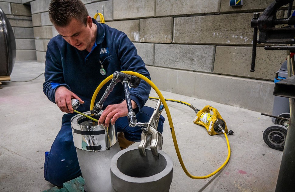
6. Transport and Exposure Containers
Radioactive sources incessantly emit hazardous radiation in all directions, unlike X-ray tubes, which can be turned off. This generates a need for stringent guidelines and transportation in an encapsulation of radiation-absorbing material, which is regulated by a legally established criterion.
Exposure containers have similar guidelines and are required to be robust, foolproof, and dirt-proof, undeterred by physical impacts. It should be designed to serve its purpose even if the radiation-absorbing material is damaged or impacted in any way.
The casing material usually has a high melting point (Steel). Shielding materials may include lead and sintered materials with high tungsten content, which is melt-proof and easy to work with and finish. Uranium may also be used for shielding, but its low availability results in tiny exposure containers. It does, however, have radioactivity for its own, which makes it not an ideal choice in many regions.
To take the source out of its safe storage for use is a mechanism in itself, with options varying between a rotating cylinder storage or an S-channel container, both of which provide the means of safely positioning the source at a favourable exposure position.
Operating such machinery in highly populated regions has its hazards, and appropriate contingencies have been developed, such as containers with rotating cylinders and collimators where only the radiation beams required for assessment are emitted. The collimator absorbs the remainder of the radiation to secure the people in the vicinity. Such devices are called “CARE,” standing for confined area radiation equipment, or “LORA” (low radiation equipment).
Unforeseen accidents may cause damage to the capsule, resulting in a leak. To avoid such unfortunate surprises, “wipe-tests” are regularly conducted for the early detection of leaks.
Film Capture
In film radiographic testing, the film selection is dependent on the financial limitations, and more importantly, the image quality. There are various film types available in the market with different exposure factors and film system classes. The film classes deployed are dependent on the defect detection requirements. Film sizes can also vary, with special film sizes readily available in the markets, provided in vacuum-sealed packaging to avoid film faults caused due to mishandling.
The final quality of the exposed radiographic inspection films depends on the handling and storage, as even minimal preexposure to background radiation may cause foggy films. The conditions required to store films and avoid fogging consist of factors like:
- Background radiation levels below 90nGray
- Temperatures lower than 24 degrees Celsius
- Humidity below 60%
- Non-exposure to X-ray film chemicals
- Edge-stacked films
Latent images obtained as a result of X-ray radiographic testing can be converted into visible images using film processing. To do so, a dark room is required, in close proximity to the exposure location, devoid of light, with a light trap at the entrance. The lighting in the dark room must be carefully planned at an appropriate distance from the film, with lighting limited to normal, orange-red or green lights. The layout also requires a distinction between a dry side and a wet side to avoid chemical exposure when not necessary. Processing tanks, used in manual processes, may be made of stainless steel or plastic with appropriate dimensions to accommodate the films. The wet side of the dark room consists of the following;
- Developer tank
- Stop bath or rinse tank
- Fixer tank
- Final wash tank
- Tank for the wetting solution
Recently, film processing has been automated for industrial X-ray radiographic testing film handling. This standardises the procedure, reducing the chances of error and providing faster results.
The film archiving properties may be checked using the Thiosulphate test. Exposed films, too, require storage in ambient environments to retain image quality.
Image Quality Indicators (IQIs)

Filters and intensifying screens are essential to reduce the negative effects of radiation on the obtained image and help manipulate the radiation to adjust contrast. Objects with defects may result in shadowy images. Radiographic Film Examination of cylindrical objects may also result in scattered radiation. Scattered radiation can be managed by adjusting the size of the radiation beam using a diaphragm in front of the tube window. A cone (collimator) can also be used to localise the beam. Masks (lead strips) may also be used around the edges of the objects.
Image quality may be manipulated using radiation filters, which are metal plates, often made of lead or copper, placed between the tube window and the objects, lowering the image contrast because of radiation hardening.
Image quality is governed by the contrast, sharpness, and film graininess, wherein the defect discernibility is affected by the radiation quality, film properties and viewing conditions.
The image contrast is affected by factors like:
- Thickness variations in the test subject
- The radio-opacity of the specimen and the defects within it
- The location and shape of the defects,
- The radiation quality
- The extent of scattered radiation
- The effect of the filters employed.
The film type and density affect the film contrast. Whereas, the sharpness may be affected by the following:
- The size of the focal spot
- The source-to-object distance
- The object-to-film distance
- The contact between film and intensifying screens
- The kind of intensifying screen
- The radiation energy used.
The graininess, on the other hand, depends on:
- The emulsion layer thickness,
- The silver-gelatine ratio in the emulsion
- The size of the silver crystal
- Radiation energy
- The film development process.
Image Quality Indicators(IQI) are placed on the source side of the object under inspection. If not possible, it may be placed on the film side, with an indication. The material of the indicator must also be identical to the test subject.

The image quality is defined as the number of the thinnest visible wire. The four most commonly used types of IQI are:
- Wire type
- Step-hole type
- Pentameters, which are small plates with drilled holes.
- Duplex IQI
Densitometers may be used to assess the optical density in sections of the radiographic film.
IQI sensitivity values are dependent on the IQI type and the thickness of the object. When provided as a percentage of object thickness, a lower value indicates better quality.
Radioactive Material and Handling

The International Atomic Energy Agency (IAEA), specifically the International Commission of Radiation Protection (ICRP), dictated codes on ionising radiations that have been adopted globally. Protection from unwanted radiation relies on three principles:
- The speed of exposure, with the aim for shorter exposure durations
- The distance of operators and personnel from the radiation location
- The employment of shielding and collimating techniques to reduce exposure.
This helps limit the permissible radiation exposure to 20 mSv/year for category A radiology workers. To ensure accurate monitoring of radiation exposure, instruments are used for measurement, such as:
- Dose rate meters
- Scintillation counters.
For personal protection, instruments like Pendosimeters (PDM), Thermoluminescent badges (TLD) and Film Badges are employed.

Radiological workers are also required to wear dose meters to register the doses of radiation received over specified time periods. Apart from this, shielding measures are taken to achieve an intensity reduction, which may include:
- Demarcation barriers
- The erection of an absorbing barrier
- A combination of the above
X-ray radiographic testing and Gamma Ray radiographic testing have expanded the potential of the NDT industry, aiding in versatile applications. With intensive care and research, the industry has managed to develop plans, technology and safety measures to compensate for the few demerits of this method. Conventional film radiography has stayed relevant despite the development of methods like Computed Tomography and Digital Radiography, emphasising the utility and benefits provided by this method.
References
- Bardal, Einar, and J. M. Drugli. "Corrosion detection and diagnosis." Materials science and engineering 3 (2004): 144-164.
- R.P.Wardhani, “Radiographic Examination Procedure as Non-Destructive Testing Method in Process Piping” (2019), Mecha Jurnal Teknik Mesin, Vol. 2, No. 1
- Halmshaw, R. 1982. "Industrial radiology - theory and practice." United Kingdom.https://books.google.co.in/books?hl=en&lr=&id=wJqBSA1exqoC&oi=fnd&pg=PR9&ots=9moi5CmfQx&sig=sGVNoIC4OVPp98dw_4epKsqSB4s&redir_esc=y#v=onepage&q&f=false
- Industrial Radiography Image forming techniques, GE Inspection Technologies
- Real Time Radiography and Radioscopy, BINDT, https://www.bindt.org/What-is-NDT/Real-time-radiography-and-radioscopy/
- Srivastava, S. P., et al. "Conventional radiography: a few challenging applications." Barc newsletter 285 (2007): 174.
- Miller, Charles Walter. "Industrial radiography and the linear accelerator." Journal of the British Institution of Radio Engineers 14.8 (1954): 361-375.
- What are Image Quality Indicators (IQIs), Baker Huges, https://www.bakerhughes.com/waygate-technologies/blog/what-are-image-quality-indicators-iqis
- Kumar, Anish, and Walter Arnold. "High resolution in non-destructive testing: A review." Journal of Applied Physics 132.10 (2022).
- Aastroem, Thomas. "From fifteen to two hundred NDT-methods in fifty years." 17th World Conference on Nondestructive Testing. 2008.
- Hanke, Randolf, Theobald Fuchs, and Norman Uhlmann. "X-ray based methods for non-destructive testing and material characterisation." Nuclear Instruments and Methods in Physics Research Section A: Accelerators, Spectrometers, Detectors and Associated Equipment 591.1 (2008): 14-18.
Key Takeaways
- Conventional Radiographic Testing relies on the penetrative ability of ionising radiation, such as X-rays and gamma rays, to detect internal flaws in materials, making it invaluable in structural integrity assessment.
- Radiographic Testing employs sophisticated equipment, including X-ray tubes, radioactive sources, exposure containers, and image quality indicators (IQIs), all contributing to high-resolution defect detection and safety-compliant practices.
- Handling of radiation sources mandates stringent IAEA-aligned safety guidelines, with protective barriers, dosimetry tools, and film archiving standards ensuring both operator safety and inspection fidelity.
FAQs
What is the main difference between X-ray and gamma-ray radiographic testing in NDT?
X-ray testing uses electrically powered X-ray tubes to produce radiation, allowing control over energy levels and exposure time, while gamma ray testing utilises naturally or artificially radioactive isotopes, which emit radiation continuously and do not require a power supply.
How is image quality ensured in conventional film radiography?
Image quality is optimised using Image Quality Indicators (IQIs), radiation filters, proper film selection and handling, and environmental controls like temperature and humidity. IQIs, including wire and duplex types, help verify contrast, resolution, and defect detectability on the film.


