
Table of Content
- Introduction
- Dealing with Material Thickness
- Measurement Techniques
- Considering the Magnification Effect
- Countering the Over Saturation/Blooming Effect
Introduction
Frequent NDT Pipe Inspection is aimed at assessing any changes to the pipe wall thickness, which involves testing for corrosion and erosion as well as examining the quality of welds in pipes.
Over time, Corrosion from the outside, erosion from the inside in addition to pressure applied by gases or fluids flowing through a pipe may affect the pipe’s original wall thickness.
Even the slightest change can affect the pipe’s ability to withstand pressures and meet relevant operation requirements. This degradation may cause faster development of cracks and even total pipe collapse.

There are a number of challenges presented to Non-destructive Testing operators when attempting to measure wall thickness using Digital Radiography: The amount of material that needs to be penetrated for a good inspection, the blooming effect (penetration vs. saturation), and the implications of magnification (distortion and unsharpness).
In its ongoing quest to develop user-friendly tools for NDT digital X-ray, Vidisco has introduced a new wall measurement tool, integrated into its XbitPro & VEO PRO software, which overcomes these obstacles.
Dealing with Material Thickness
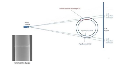
When there is a huge difference between the minimal thickness of material to be penetrated for the outer wall identification and the extensive amount of material to be penetrated for the inner wall identification, it creates a conflict in X-ray exposure/ dose (energy level and time) for each of these measurements.
Vidisco’s Digital Radiography software enables the automatic grabbing of more than one image and gathering all the data necessary for exact tangential wall thickness measurement and double wall inspection, as well as automatic measurement calibration methods.
Measurement Techniques
Using the Tangential Technique, pixels can be measured. Using double-wall measurement, grey levels (intensity) can be measured.
In both cases, the data is converted into real numeric measurements for the operator, either inches or millimeters.
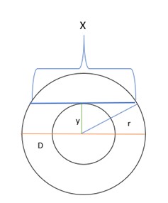
The tangential technique measures pipe diameters and wall thicknesses.
A common mistake regarding this technique is that the amount of material that must be penetrated is equal to double the thickness of one of the pipe’s walls.
According to this assumption, if the pipe’s wall thickness is 3mm, then one would need to penetrate 6mm of steel to achieve accurate measurements. This assumption is incorrect.
When dealing with the outer wall, the thickness of steel requiring penetration is nearly zero.
In the case of the pipe’s inner wall, the opposite is the case. To acquire accurate measurements much thicker steel should be penetrated, as shown in the diagram below.
The double wall technique is very useful when aiming to identify and measure wall loss, pitting, etc. In this case, the final results are provided in millimeters or inches and a comparison is carried out in to measure differences in grey level.
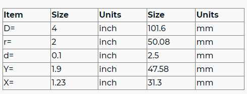
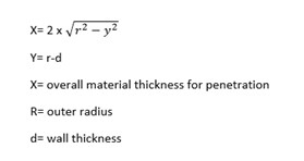
For example, a 4” pipe with 2.5mm wall thickness will be required to penetrate at least 31.3mm of material – i.e. over 6 times the thickness of the two walls needs to be penetrated in order to see the inner wall of the pipe.
Considering the Magnification Effect
Magnification is equal to the distance between the source and the DDA imager (a + b) divided by the distance between the source and the measuring point (a).
Due to the pipe’s round shape and the work method used in tangential measurement, a distance is created between the measurement point and the detector, indicated by distance b.
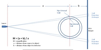
Two problems arise due to the distance between the DDA and the measuring point (b). First, the wall projection on the image is larger than the actual pipe wall thickness.
Second, the image gains unsharpness. The farther the pipe is located from the panel, the greater the magnification effect and increase in unsharpness will be.
The problem is compounded if the pipe is covered with insulation.
Using the wall measurement tool, an object with predefined dimensions is placed on the same plane as the pipe’s center which enables completely automatic calibration of the grabbed X-ray images.
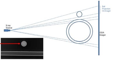
To obtain the measurement, the user simply needs to enter the object’s dimension. Vidisco provides a steel sphere with a precise 1-inch (25.4 mm) diameter for this purpose. The round shape effectively prevents projection distortions.
Another option enabling automatic calibration of measurements is to use the pipe itself, if the exact diameter of the pipe is known and its outer layer is smooth and free of corrosion.
The calibration and measurement process is also completely automatic when using the pipe itself for calibration purposes – the pipe’s diameter only needs to be entered once to generate the process.
Overcoming the phenomenon that accompanies magnification/unsharpness is possible by applying an automatic mathematical algorithm that systematically marks the exact location of the inner and outer walls within the unsharpness and accurately measures the distance between the two points.
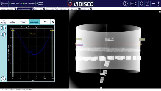
In the above image, a line profile display of the measuring point applied by the user where the automatic algorithm is implemented is shown.
After completing the calibration (calculation of the magnification factor,) the user can measure the pipe diameter and a projection of the wall thickness, obtaining an accurate annotation of the actual pipe diameter and wall thickness after deducting the magnification effect.
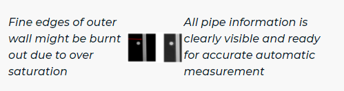
Countering the Over Saturation/Blooming Effect
Due to the wide dynamic range of digital radiography (16 bit/ 65000 gray levels) and the unique capabilities of Vidisco’s detectors.
It’s sometimes possible to find the required energy level that will enable penetration of the inner wall without saturation of the surrounding area of the outer side of the same wall – all in a single image.
This is usually achieved in small pipes with low wall thickness when using an Isotope (IR-192) X-ray source.
In order to enhance flexibility and allow the use of Isotopes (IR-192) Vidisco developed a procedure with a supporting algorithm — called Wall Thickness Macro — enabling the automatic acquisition of more than one image and the combining of all the data necessary to identify the exact location of the outer wall without saturating the surrounding area.
Vidisco’s NDT solution reduces the number of instances where it is necessary to use an Isotope (Iridium) source. In addition to the significant savings in time and money, it also ensures increased safety.
It does away with the need for night shifts or plant closures, or for special safety measures to protect operators and staff from exposure to high radiation levels.
References:
1. Vidisco’s NDT solution
2. IndustrySearch


