Blog By Charles Janecka, Associate Product Manager at Olympus. This article appears in the September/October 2020 issue of Inspectioneering Journal.
How Stereo Measurement Works
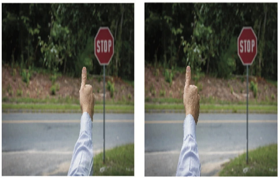
Stereo measurement works in a similar way to how human eyes interact with our brains and our environment. We avoid bumping into things when we walk around because our brain is constantly calculating distance, based on triangulation and the parallax from our right and left eyes. For example, when we look at a building and close one eye and then the other (Figure 1), our brain knows that the building has not moved, merely the perspective from each eye, based on its position in relation to the object, has changed. Using these two different perspectives of a static object, measurement becomes possible. Lateral shift is inversely proportional to distance. Therefore, the “Z” distance is inversely proportional to lateral shift. In daily life, our eyes work with our brain to achieve this understanding of how far away various objects are (e.g., a table, a chair, a car, the moon, etc.) and how large or small they are.

Figure 1. Parallax lateral shift – left eye vs. right eye views.
Applications within Remote Visual Measurement Systems
In terms of remote visual measurement, the parallax determination is calculated in a slightly different way. It does, however, use the same fundamental principles. In remote visual inspection (RVI) equipment, the brain is replaced with a charge-coupled device imaging sensor and a processor. The eyes are replaced with the optical lenses in a tip adaptor. The tip adaptor has two lens systems with a preset offset in their distances to each other. Figure 2 demonstrates how the optical system works in conjunction with the charge-coupled device and processor. The parallax is used to determine the relevant distance of an object, based on the perspective shift across each side of the charge-coupled device.

Figure 2. Parallax of a stereo image on a charge-coupled device.
Using the X, Y, and Z position data and the parallax algorithm, RVI devices apply five different measuring modes to give automatic sizing and situational information after reference and/or measurement points are selected.
These measuring modes offer the following information:
- Distance: The distance between two points
- Point-to-Line: The perpendicular distance between a point and a user-defined line
- Depth: The perpendicular depth/height between a point and a user-defined plate
- Lines: Cumulative multiple points
- Area: The area of an enclosed shape (the circumference of the lines is also available here)
Measurement Environment and Setup Accuracy
Before an inspector undertakes measurements with any equipment, it is important that the measurement environment is correctly installed and understood. The optical characteristics of the lens system used may vary on a miniature scale from lens-to-lens during the manufacturing process. As such, specific “measurement environments” are created for each individual lens system. This informs the measuring device, or scope, of the exact optical characteristics of the optical adaptor being used. Even though these components are precision-made, when dealing with optics on this scale, even the slightest variance can have an impact on the imaging. Therefore, the optical characteristics of each tip adaptor should be considered. To obtain the highest accuracy, it is possible to carry out “one-to-one” stereo matching. This is where measurement data is created specifically for a certain tip (or tips) used with a certain scope.
Super Wide Stereo
Super wide field stereo videoscopes with a greatly extended measuring area can offer a wider field of view (FOV) and deeper depth of field (DOF). Measurement accuracy can be improved with advanced measuring algorithms and 1-to-1 measurement matching. Moreover, today’s processors, in conjunction with innovative optics and more sensitive charge-coupled devices, have made real-time display an option. For example, a five-point object distance meter with multispot ranging (Figure 3) and greater processing power can provide multiple measurement modes on one image.

Figure 3. Five-point spot ranging
Super wide field stereo measurement has changed the parameters for conducting a measurement, which can now be taken (within specification) of larger defects from a larger target distance. Traditionally, the measurement range was between 5 mm to 30 mm, however newer wide field stereo measurement increases the range from 4 mm to 60 mm. In addition, wide field stereo measurement can increase FOV by 1.5 times and DOF by 1.7 times. This equates to a four-times wider measurement area when compared to traditional stereo measurement options.
With this kind of increase in FOV and DOF, inspection time can be drastically reduced, as it gives inspectors the ability to capture a complete defect in one attempt. It eliminates the need to capture multiple images and measurements of the same defect because of a narrow field of view or the historic requirement of close proximity to the target object. Time is a major factor when undertaking any borescope inspection, in any industry. The more efficient an inspection can be in terms of speed, precision, and even cost of inspection/ownership, the better.
Importance of 3D Modeling
Accuracy and precision are the two most important aspects of any type of measurement. As previously described, great advances have been made to improve these in the field of remote visual measurement. However, picking the correct measurement point is just as important.
Advances in the field of RVI have been made in lensing, illumination, and imaging, such that the resulting measurements are more precise than ever. This precision, though, is only as good as the point picked. Modern videoscopes are only able to take measurements based on the points provided to them by the inspector, making the inspector, in a way, a part of the measurement system itself. 3D modeling can help make this process easier and more efficient.
Picking the correct point is crucial, as there are certain applications where not picking the appropriate point can have dramatic results. One such case is in measuring the edge of a surface. If done improperly, the point can “fall off the edge,” leading to inaccurate results.
It is not always easy to know the shape of what you are inspecting. The very nature of measuring off an image is that the image screen is two-dimensional. When an inspector is picking points, this two-dimensionality can be problematic because it makes it difficult to precisely select the location to measure depth-wise. The effect of this is that the videoscope may measure a distance that is different than what the user wants. For example, in Figure 4, missing material is being measured. The point placement needs to be on the edge of the missing material. It is not immediately obvious if this point is on the edge since the view includes the corner and two sides of the material.
*Note that it is not immediately obvious on which side of the material the green square lies in Figure 4.

Figure 4. Missing material.
When a videoscope has 3D modeling, the inspector can rotate the model so they can be sure where the point is positioned. Note in Figure 5 that the same part (as shown in Figure 4) has had its 3D model rotated so that it becomes more obvious that the point (green square) is on the edge of the missing material.

Figure 5. Missing material rotated.
3D modeling also enables inspectors to rapidly evaluate the entire surface of what is being measured. They can quickly pinpoint problem areas that require more attention. This capability can dramatically speed up the inspection time and produce more reliable, robust measurement results. One example of this is weld inspection, where issues such as undercut can be evaluated more quickly using 3D modeling.
See an example of this in Figure 6. The 2-dimensional image of the weld undercut is on the left (where the measurement is performed) and the 3-dimensional image is on the right. Imagine having to determine and measure the undercut using only the 2D image. To do so effectively, an inspector would have to measure numerous points all along the edge of the weld. This would produce an effective measurement, but would be very time-consuming.

Figure 6. 2D image vs. 3D modeling of welds.
Figure 7 is a 3D model of the same weld as in Figure 6. The difference is that the 3D model has color depth mapping applied to it. The triangle on the left image denotes the reference plane. This reference plane is on the base material.
An inspector can now see at a glance which areas need further inspection and measurement. The area in blue denotes portions of the 3D model that are above the plane. In Figure 7, this is the weld. The area in red denotes portions of the 3D model that are below the reference plane. In Figure 7, the dark red areas indicate undercut. Using this visualization tool, the inspector can avoid spending time searching. All that is needed now is to focus time and effort toward measuring the dark red areas.

Figure 7. Measuring weld undercuts.
Summary of Stereo Measurement Advances in RVI
Advances in charge-coupled device size, optics manufacturing, and point-matching algorithms can all be combined to create a new super wide field stereo measurement system. With measurable areas as much as four times greater than what was previously attainable, newer and larger measurement types can be taken. The ability to measure from farther away also makes it easier on the RVI inspector to get to the target and take a stereo image. Less time is spent trying to get close enough for a satisfactory image.
A videoscope that measures precisely is only effective if it measures the correct point. Further advances in 3D modeling enable the inspector to take that easily made stereo image and measure with confidence using the model. This means the inspector not only knows where their point resides, but is more aware of what the videoscope is measuring. The inspector can also use features such as color depth mapping to evaluate the image as a whole and determine which areas to focus in on.
These factors combine to create a stereo measurement system that is easier to use and able to provide more precise measurements than ever before.


