Corrosion Mapping
Using the HydroFORM for External Corrosion Mapping
Published on 1st August 2023

Introduction
The interior and exterior surfaces of carbon steel pipes tend to corrode over time, regardless of their environment. Regular inspection of this corrosion is required to assess and monitor pipe integrity.
The HydroFORM® corrosion scanner is especially useful for measuring the remaining wall thickness of pipes. When paired with a phased array instrument, such as an OmniScan® flaw detector, using the HydroFORM scanner is an efficient way to inspect corrosion as it can provide precise measurement of the remaining material by taking into account the external and internal surface reflections. The OmniScan flaw detector analyzes the ultrasound reflections and calculates the delay between the external and internal surface echoes to provide the remaining wall value at every 1 mm × 1 mm point.
However, in some circumstances, inspectors only want to measure the external corrosion, or they need to distinguish between the external and internal corrosion’s contribution to the remaining wall value.
Challenge
Taking manual measurements of surfaces, such as with a pit gage, is time consuming and operator dependent. The measurement results can vary from user to user and from inspection to inspection. Inspectors need a more reliable method for a faster, more efficient inspection. The use of lasers to measure external corrosion requires a major investment in equipment and training. Furthermore, laser inspection is incapable of providing a complete assessment of pipe integrity as it cannot reach the pipe’s internal surface. This limitation means that laser inspection must be supported by more than one system/technology, which can lead to training, data management, and inspection team coordination challenges.
Solution
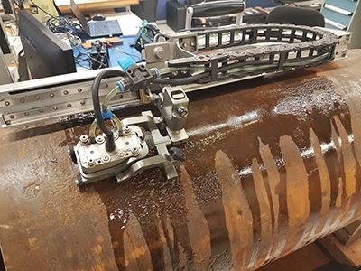
The HydroFORM scanner is a proven solution for inspecting internal corrosion in pipes. With its water-column feature that eliminates the need for a wedge, the HydroFORM scanner provides the benefits of a phased array immersiontank inspection. It offers excellent surface conformance and coupling conditions, even on rough surfaces.
When the HydroFORM scanner is used with a multigroup instrument, external corrosion can be mapped at the same time as internal corrosion (remaining wall) in one scan. The first group is optimized for internal corrosion while the second group (using the same probe) is optimized for external corrosion mapping. This provides two distinct C-scans that can be analyzed directly on the OmniScan flaw detector, on a computer using OmniPC™ software, or exported independently in CSV format. Spreadsheet software can then be used for post-processing.
Typical Procedure
The procedure for external corrosion mapping is similar to a typical HydroFORM® scanner application but with a few parametric differences.
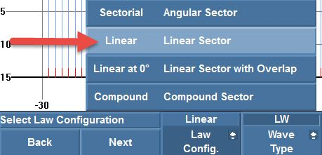
First, an internal corrosion (remaining wall) group needs to be created by setting the law configuration of the first group to “Linear” instead of “Linear at 0°.” The angle of the inspection is 0°.
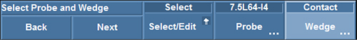
Then, to create the second group for external corrosion, the settings for the first group should be copied but the wedge parameter changed to “Contact.” This setting enables inspection of the outside surface of the pipe through the water column.
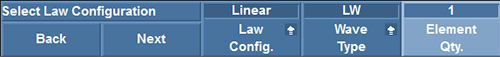
The element quantity is set to one element per beam.
The first and last elements need to be set according to the following formulas to ensure that both groups have the same total aperture and cover the same position on the part:
First element:
Element Qty (First group)
2
Last element:Total number of elements of probe —
Element Qty (First group)
2
In the example below (Fig. 4), four elements were used in the first group, so the first and last elements of the second group were set to two and sixty-two elements, respectively.

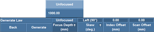
The focus depth parameter is not relevant as the beam cannot be focused with only one element per beam. For reporting purposes, this parameter is set to unfocused.
The velocity must be adjusted to enter the value for water (1480 m/s, or 0.0583 in./μs). This helps ensure the accuracy of the depth values.

A probe is placed on a corrosion-free area of the pipe, and the wedge delay is manually adjusted, so the front wall is at 0 mm.
Because only the surface of the part is considered and ultrasound attenuation in water is marginal, no time-corrected gain (TCG) is required on the second group.
As gate synchronization cannot be used for the external corrosion group, it is important to have a stable probe holder system such as an Olympus HydroFORM® and MapROVER™ scanner assembly. Moreover, an unstable probe holder system could drop in a large depression on the part, causing the nominal reference to be lost.
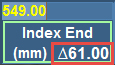
Scan lines cannot be overlapped in linear mode. Therefore, it is important to note the index delta in the Index End parameter of the Scan>Area menu of the first group (internal corrosion) to correctly set the mechanical index step.
Results
Corrosion Data on a Corroded Sample
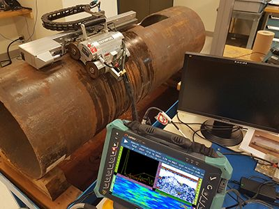
The tested sample was a 20 in. (508 mm) OD pipe with a nominal wall thickness of 0.35 in. (9 mm) with corrosion on the inner and outer surfaces. The scan was performed on the circumferential axis on the outside diameter using an assembly consisting of the HydroFORM scanner and MapROVER automated scanner. The surface was covered with a resolution of 1 mm × 1 mm.
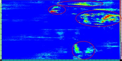
S-scan and C-scan views were used to visualize the corrosion. The first group’s C-scan (Fig. 10) was used to visualize the remaining wall value, taking into account the internal corrosion. The blue color in the C-scan represents the nominal thickness, and the remaining wall becomes thinner as the color progresses from yellow to orange to red. In the C-scan, there are four areas where we can identify noncoherent data. These areas represent where the external corrosion disrupts the ultrasonic signal.
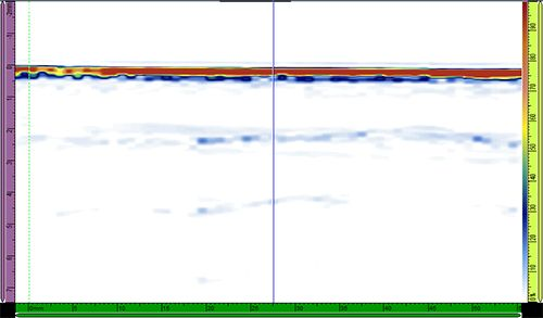
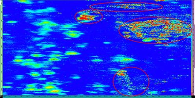
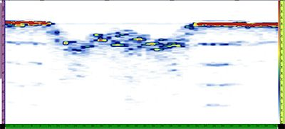
With the second group, we can see the external corrosion in both the S-scan (Fig. 12) and C-scan (Fig. 11). For this example, which uses a custom color palette (a typical corrosion inspection palette), the redder the color, the deeper the external corrosion. The external corrosion is easily identifiable, and it correlates with the remaining wall C-scan acquired by the first group.
Conclusion
With this new inspection procedure using the Olympus HydroFORM scanner, external corrosion can now be mapped during a typical internal/remaining wall corrosion inspection. A second group optimized for external corrosion measurement can be created using the OmniScan MX2 flaw detector. External and internal (remaining wall) corrosion data can also be exported to a CSV file for further analysis. This method can reduce the time it takes to perform corrosion inspections and avoid the training and investment required when multiple inspection technologies are used.


