Ultrasonic NDT
Ultrasonic Velocity and Attenuation Measurements in Geological Samples
Published on 9th April 2021

Application
Ultrasonic velocity and attenuation measurements in geological samples, such as rocks and minerals.
Background
Ultrasonic sound transmission techniques have been utilized to define the mechanical properties of geological materials. Specifically, these techniques have been used to quantify the physical parameters, such as hardness, elastic modulus, and grain structure, of the material. These techniques have also been used to monitor the compaction of soil or sand under laboratory conditions. These tests can typically be performed on prepared specimens with two flat, parallel surfaces using through-transmission techniques with low-frequency transducers, as described below. Field tests are normally performed at seismic frequencies well below the ultrasonic range.
Equipment
Prepared geological samples can typically be tested with ultrasonic instruments such as the Olympus EPOCH 650™ flaw detector. Pairs of low-frequency contact transducers are employed in both longitudinal and shear wave modes. The specific transducers used in a given case will depend on the acoustic properties of the test materials and the sample dimensions, but frequencies of 1 MHz and below are most commonly employed. The frequency should be selected to provide undistorted waveforms in addition to adequate penetration.
Procedure
Samples may be prepared in a variety of shapes and sizes as long as they have two flat, parallel surfaces for transducer coupling. Commonly, they will be cylinders or blocks with thicknesses ranging from approximately 2 in. (50 mm) to 10 in. (250 mm) in the direction of measurement. Sample diameter or width should be larger than the element size of the transducer being used. Through-transmission testing with separate transmitting and receiving transducers is normally employed due to the high level of scattering exhibited by most geological materials at ultrasonic frequencies. Set the instrument’s pulser to through mode and adjust gain and filtering for best response. In through-transmission tests, the probe zero delay can be determined by touching the two transducers together and using that signal as the zero point. Gel couplant is useful for longitudinal wave testing to minimize absorption into porous samples. Special high-viscosity couplant, such as Olympus’ SWC-2 shear wave couplant, must be used for coupling shear wave transducers.
Pulse transit time can be measured with either a flaw detector or an oscilloscope or digital waveform display connected to a pulser/receiver. Flaw detector software can also calculate velocity and measure.

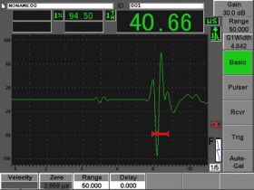
One-way transit time measurement in 3.75 in. (95 mm) sandstone tested with an EPOCH 650 flaw detector, two V102-SB longitudinal wave transducers, and two V152-RB shear wave transducers (both 1 MHz, 1 in. diameter).
The measured velocities along with material density can be used to calculate elastic properties as described in the Elastic Modulus Measurement application note. Attenuation is correlated with physical properties like grain structure or micro-cracking experimentally, using reference samples representing known conditions to establish a calibration curve.
Products used for this application
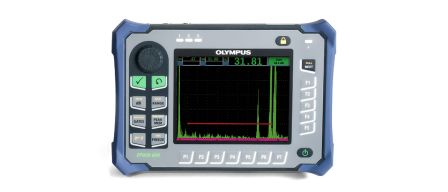
The EPOCH 650 is a conventional ultrasonic flaw detector with excellent inspection performance and usability for a wide variety of applications. This intuitive, rugged instrument is a continuation of the popular EPOCH 600 flaw detector with additional capabilities.


