Bolt Inspection
Riser Bolt Inspection with Creo Bolt Scanner
Published on 11th May 2023

Sonatest performed Phased Array Ultrasonic Testing on one Riser Bolt. A TFM scan was also implemented to increase resolution and flaw fidelity. The bolt can be tested from either end, without removing the bolt from production for testing.
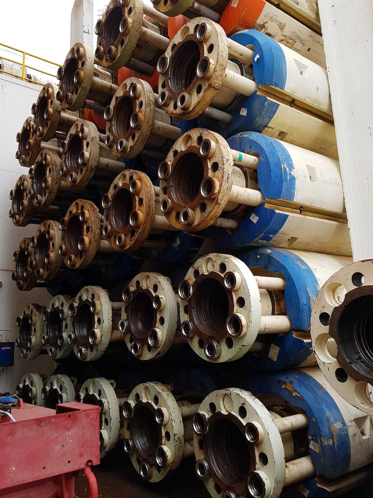
Riser bolts are an essential, critical component of offshore drilling structures. Their integrity is vital to the safety and efficiency of the riser system. The Creo Bolt Scanner allows the inspector to fully test each bolt using a simple setup, from one end of the bolt, to achieve a recorded, reliable, repeatable scan. This inspection replaces the need to remove each bolt from either the riser itself or the shipping crate to perform visual and penetrant testing, saving time and increasing productivity.
Technical Information & Requirements:
The riser bolt is 3.5” in diameter and 16.5” long. Several notches were added to the bolt to replicate flaws on the bolt.
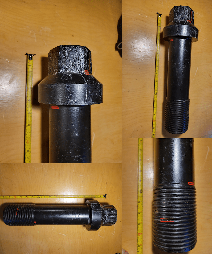
Fig. 1 – Riser Bolt
5 Flaws were added to the bolt. All flaws were approximately 3/8” to 5/8” long and 1/16” deep, except for one 1/16” hole drilled approximately 5/16” deep. The bolt was scanned in a circular pattern. The bolt was marked directly above the text on the head of the bolt for a start/stop position.
All flaws are located below according to clock position, starting at noon and scanned clockwise. The encoder was calibrated to record 12” for one rotation around the bolt, to easily correlate clock position to scan position (i.e. 4.5” scan position is 4:30 clock position).
Due to the length of the bolt, two different PAUT scans were performed simultaneously using two different focal depths. The focal depths were chosen to correlate with the areas where flaws are most likely to occur: The bottom of the bolt head and the top of the threads. Because these areas already have inherent reflectors, we are looking for signals that only occur in small areas of the scans, not all the way around the bolt. This could cause certain flaws (shallow in depth and extended in length), to be missed.
The system used for the riser bolt involves the Creo Bolt Scanner, Sonatest Veo3, and one X2B 5MHz 32element transducer with no wedge. 0–30˚ Sectorial Scans were used.
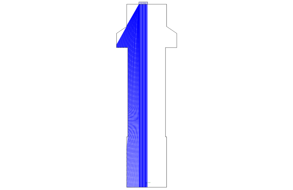
Fig. 2 – Scan Plan
In addition to PAUT, Sonatest employed TFM (Total Focusing Method). TFM adds the benefit of Full Matrix Capture, increasing the Signal to Noise ratio, ignoring internal geometrical reflections, better flaw integrity, and better resolution between nearby flaws. Two different TFM scans were used. One for the top half of the bolt and one for the bottom half. Using smaller TFM scans increases sample resolution of both scans.
Inspection Results:
Here are the results found with the Creo Bolt Scanner using the X2B 5MHz 32-element probe. These scans show the added stability and reliability gained when using the Creo Bolt Scanner compared to a manual scan. Due to the bolt geometry, the bottom of the hex pattern and the bottom of the bolt head are both known reflectors, but the flaws in these areas are still easily detected, unlike some other NDT methods which may miss small linear indications near changes in geometry like Magnetic Particle or Dye Penetrant Testing.
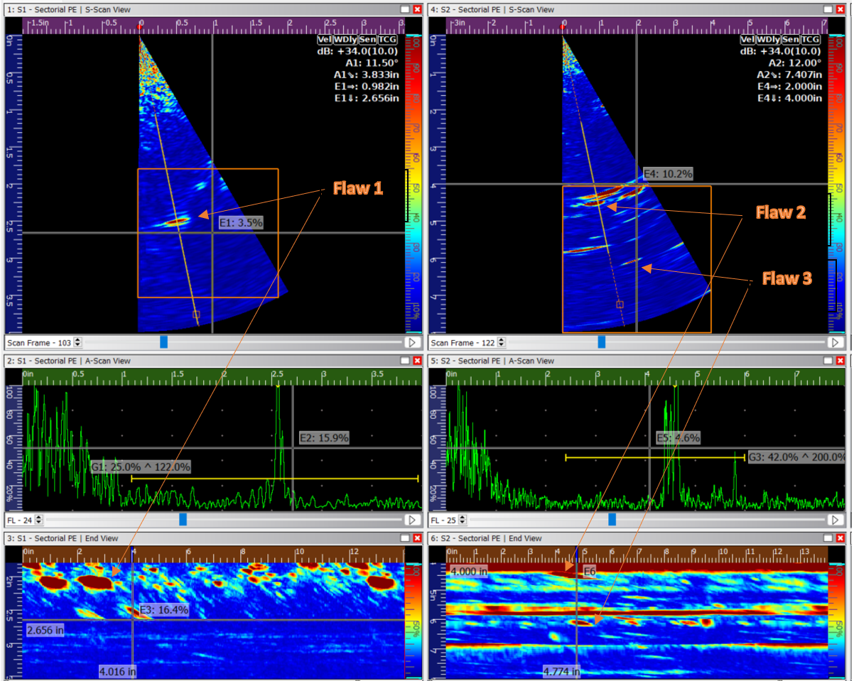
Fig. 3 – PA Scan of Top Half of Bolt
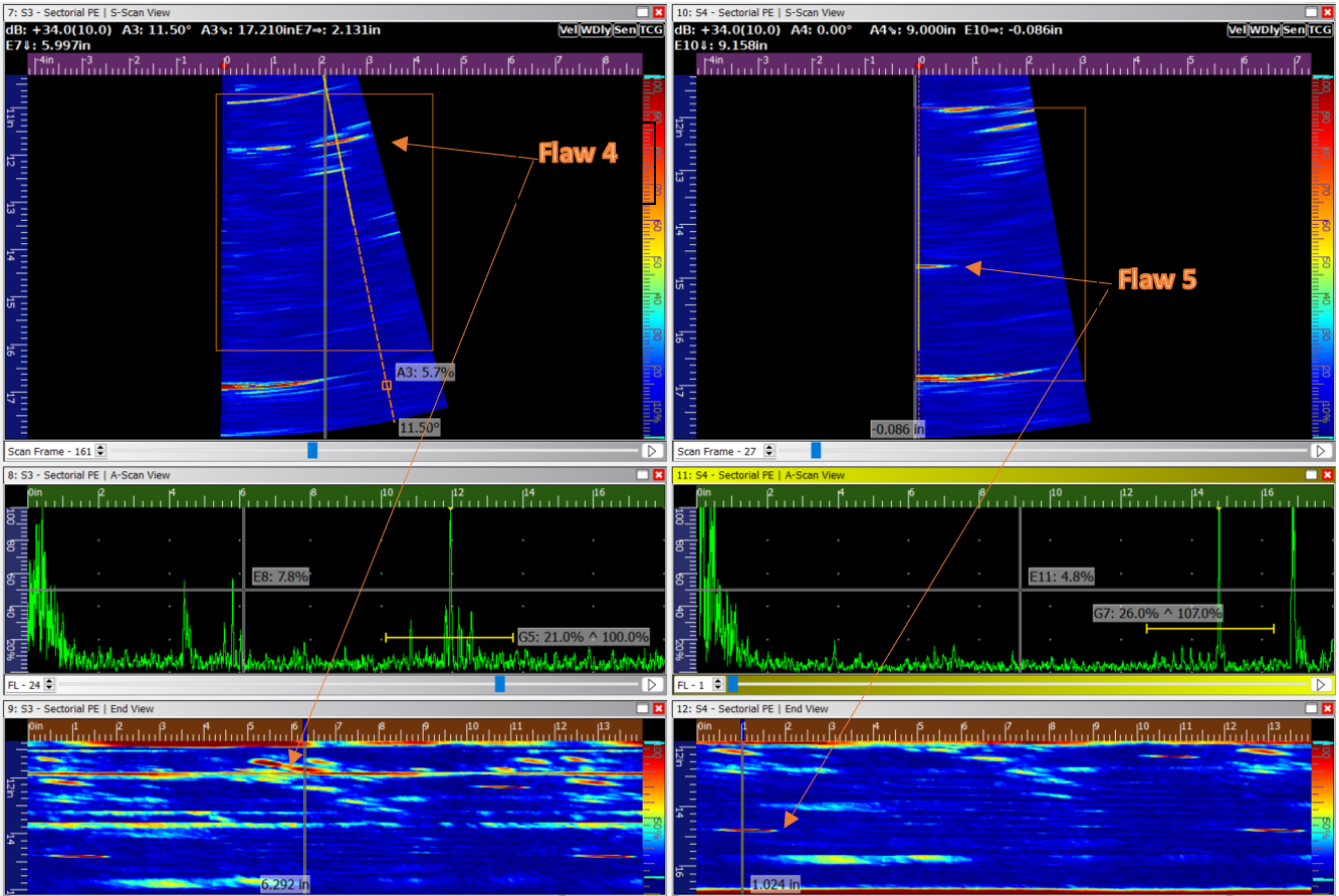
Fig. 4 – PA Scan of the Bottom Half of Bolt
Similar to the top half scan, the threads are known reflectors that often hide small linear indications like cracks within the threads, but can be easily detected with Phased Array.
The TFM scans show the flaws more clearly, ignoring some geometrically inherent reflections.
Top half TFM shows flaws 1 and 2. Flaw 3 was not seen quite as well with this scan due to the smaller probe, but will be easily detected with the larger probe that is also available with the bolt scanner. The second TFM scan shows both flaws 4 and 5.
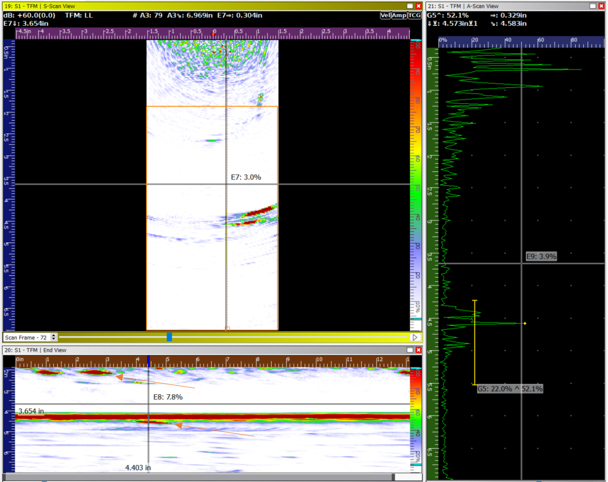
Fig. 5 – TFM Scan of Top Half of Bolt
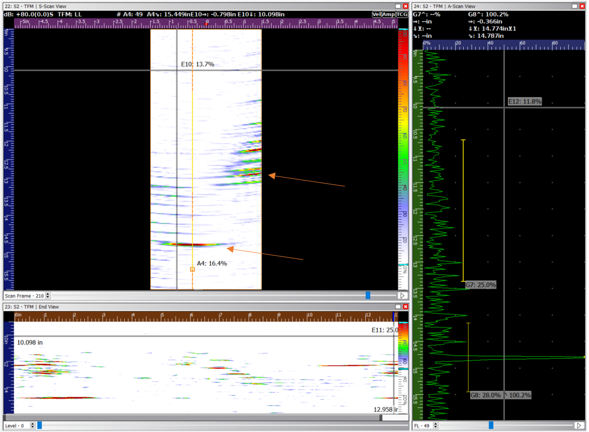
Fig. 6 – TFM Scan of Bottom Half of Bolt
Lastly, below is a scan recorded with the probe located centrally on the bolt rather than rotated around the exterior circumference of the head. This scan is focused only on the threads of the bolt, between 10” and 16” depth. Both flaws stand out extremely well using this deep penetration method.
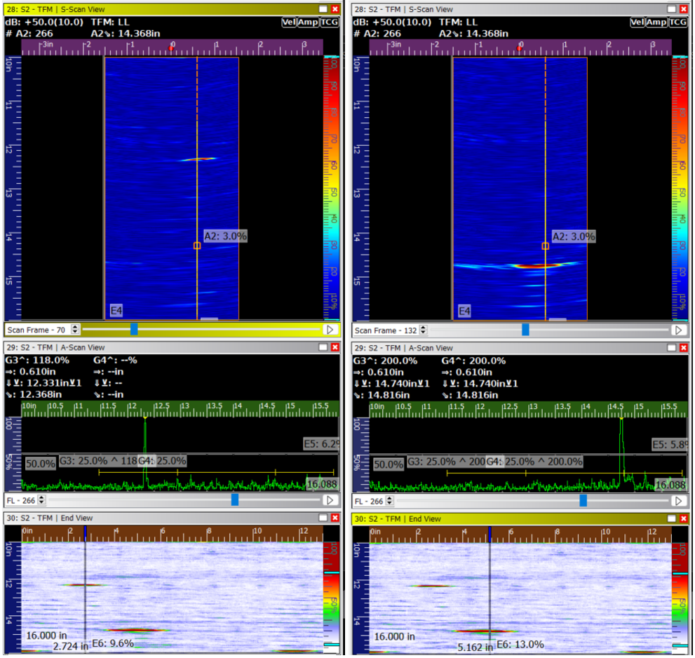
Fig. 7 – TFM Scan focused on Threaded Area of Bolt
This scanner can be used for bolt integrity checks during bolt manufacturing, inspecting in-service bolts for fatigue cracking or corrosion, or in between uses to ensure bolt soundness prior to the next implementation.


