Infrared Thermography testing
Analysis of Ballistic Impacts on Composite Materials by Infrared Active Thermography.
Published on 19th May 2023

In this study, we investigated the assessment of the damaged area on composites ballistic plates subjected to high velocity impact. The active pulsed thermography technique was used for performing post-mortem analysis of the impacted specimens. Quantitative analysis of the damaged areas shows consistent results with the size of the projectile suggesting high precision of the quantification done in this work. This quantitative defect analysis combined with knowledge of projectile velocity allows for characterization of absorbed energy and differentiation of generated defect types. This allow for the evaluation of material efficiency in spreading absorbed energy over large areas. Our observations indicate that high velocity shots tend to induce smaller impact damage areas characterized primarily by fiber breakage, while low velocity shots tend to induce larger impact damage areas featuring predominantly delamination and matrix cracking damage mechanisms.
Introduction
Since the beginning of the last century, ongoing advances in materials engineering have led to an unrestrained development of new technologies. Composite materials are among those materials attracting the most attention due to significant advantages over their homogeneous counterparts. These advantages include high specific stiffness and high specific strength combined with a significant reduction in weight, making composite materials attractive for many industrial applications. One of the most important fields of application is the defense industry where composite material properties such as low weight, rigidity, strength and durability are of key importance. Composite materials made from artificially obtained high-strength fibers are particularly interesting for high-performance defense applications including ballistic protection applications.
Analysis of the extent of damage caused to a ballistic plate post-impact is of paramount importance for the research, development, and evaluation of composite protection equipment. Infrared thermography test methods are particularly effective for post-impact characterization of composite materials as they allow for non-destructive evaluation of damage to the internal structure of the composite material.
This work discusses the assessment of damaged areas on composite ballistic plates subjected to high velocity impact using Infrared active thermography techniques. Quantitative defect size and depth analysis were correlated with projectile velocity to characterize material efficiency in spreading absorbed energy over large areas.
Telops Active Thermography Solutions.
Telops has recently developed an Infrared Active Thermography Solution called TESTD. The TESTD series offer non-destructive testing (NDT) solutions for the evaluation of components or assemblies for subsurface defect detection without material damage. TESTD combines high-capability thermal infrared cameras with different external excitation sources and a user-friendly post-processing software. Optical excitation sources such as flash and halogen lamps or lasers are available, along with electromagnetic and mechanical sources including inductive coils and ultrasound generators. Telops designs a wide range of solutions from basic systems to compact integrated systems with a variable level of automation depending on project needs and constraints.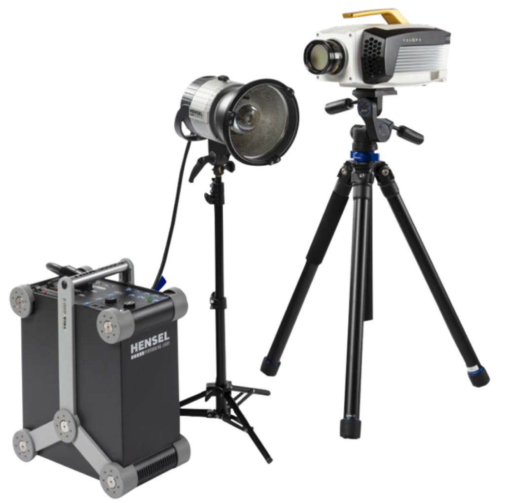
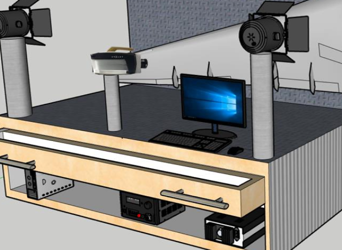
Figure 1 Telops TESTD basic (top) and compact (bottom) systems.
Composite Ballistic Sample.
The test sample used for experiments was designed for ballistic protection applications. The sample consists of a carbon fiber-nylon composite panel with an areal density of 5.45 kg/m2 and a matrix content around 35%. The specimen features a 0-90° weave and has a cross-sectional thickness of approximately 5 mm. The ballistic impacts on the specimen shown in Figure 2 are classified into 3 categories: Perforation generated at high projectile speed (green), partial perforation (red), and bouncing generated at low projectile speed (yellow).The shots marked with white squares in Figure 2 top panel were not analyzed in this work because the projectile speed was not measured during the ballistic test.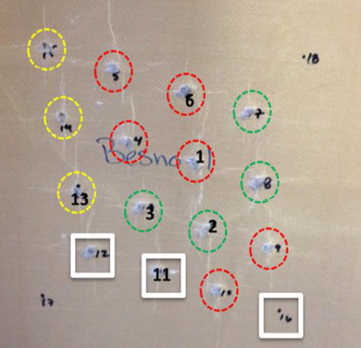
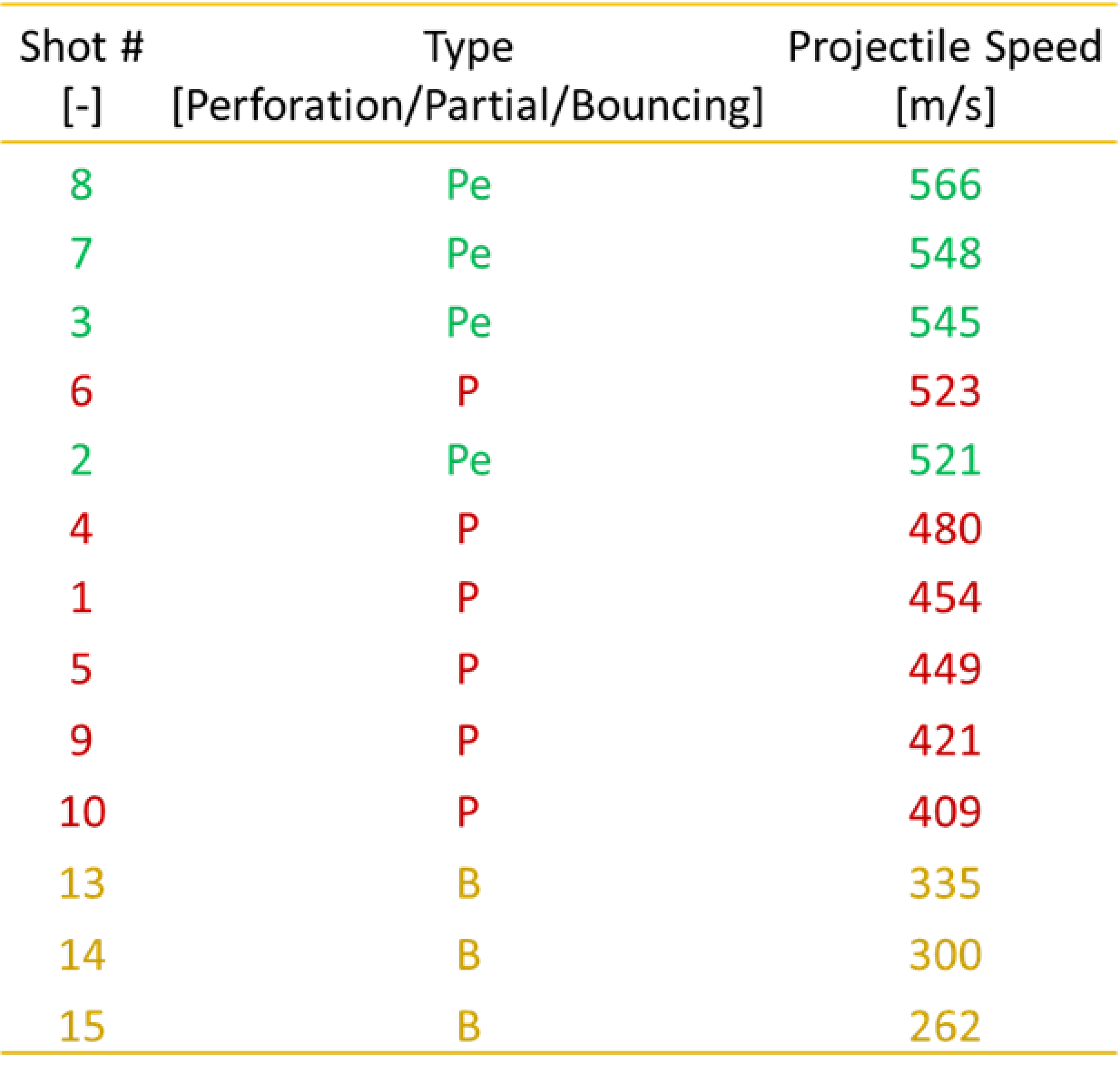
Figure 2 Composite Ballistic sample used for NDT measurements (top) and shots description and projectile speed (bottom).
Time Dependent Results.
The TESTD pulsed thermography (PT) system was used for the following analysis in reflection mode. The sample was submitted to the thermal pulse generated by the flash lamp which generated non-stationary heat flow within the sample. Figure 3 despites the thermal infrared radiation emitted by the specimen during the cooling process. The emitted radiation was measured by a Telops Fast IR camera as a function of time.
Figure 3: Thermal map of the specimen recorded after flash excitation (upper panel); and transient temperature curve of a defective (red) and non defective (blue) region of interest (lower panel).
In this work, the damage induced by the ballistic shots on the composite plate are categorized as defective area. The temperature profile for a defective and non-defective area show continuous non-periodical signal decays as shown in the lower panel of Figure 3. Few seconds after the flash excitation when the heat generated by the flash is still uniform at the surface of the specimen both areas behave similarly. Several seconds later, higher temperatures were measured in the defective zones compared to the non-defective area. This behavior can be explained by considering differences in thermal effusivity between defective and non-damaged areas. Thermal effusivity is a material property describing its ability to exchange heat with its surroundings. Thermal effusivity increases with material density. For the investigated composite sample, the defective area is a mix of lower fiber density regions with open air gaps. The thermal effusivity is lower in those regions compared to non-defective areas. Therefore, the non-defective area is expected to dissipate heat more efficiently than the defective area, which is consistent with the experimental observation. For analysis, data are transformed from the time domain to the frequency spectra using the dimensional discrete Fourier transform (DFT). This analysis technique applied to pulsed thermography is referred to as Pulse-Phase-Thermography (PPT).
Data Analysis
Telops TESTD line of active thermography products is delivered with a full-featured data analysis package called Reveal Lab. This software provides an optimized workflow to utilize a wide range of powerful functions to analyze and post-process images and image sequences. Discrete Fourier transform image processing is used to compute the amplitude and the phase images (Figure 4).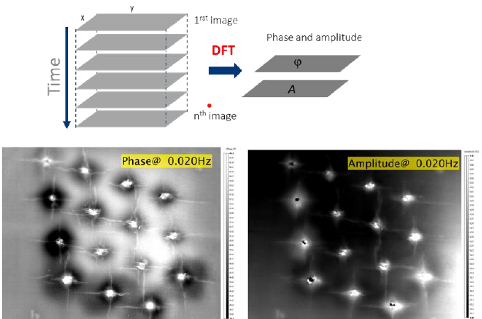
Figure 4: Workflow of the pulsed-phase-thermography technique used by Reveal Lab software and example of amplitude and the phase images computed by the software.
Phase images are particularly interesting for NDT data analysis because they are less affected by environmental reflections, emissivity variations, non-uniform heating, surface geometry and orientation. This is very important for quantitative defects characterization of materials.
Defect Type.
Figure 5 depicts a phase image of the impacted ballistic composite sample. The defects are identified by the contrast in the image resulting from their relative location in the material volume.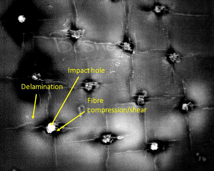
Figure 5: Phase image with different type of defects
During ballistic impact the main energy absorption mechanisms include projectile kinetic energy imparted onto the sample, and energy absorption as a result of shear plugging, tensile fiber failure, fiber debonding, fiber pull-out, matrix cracking, interlaminar delamination, and frictional energy absorbed during interaction of the bullet and laminate. The damage modes observed for the investigated composite sample are detailed in Figure 5.
Investigated Depth Range
For proper NDT material inspection, it is necessary to have knowledge of the material thermal diffusivity (). Thermal diffusivity is an inherent material property that describes the rate of heat transfer across a temperature gradient for a given material. The investigated depth range of a specimen is related to the thermal diffusion length = (/f)0.5 which represents the depth at which the amplitude of the thermal wave is reduced to e-1 of its value at the surface, with f being the modulation frequency of the excitation source. The thermal diffusivity of the investigated ballistic composite sample = cms was measured using the Parker Method. The depth range can be estimated using the expression z = C1. = C1. (/f)0.5 where C1 is an empirical constant. It has been observed that, C1=1 when using amplitude data [1], while C1=1.82 is typically adopted when working with phase data [2,3]. Figure 6 shows the depth range for the investigated composite sample as a function of the optical excitation frequency. Lower frequencies allow inspection of deeper defects into the material.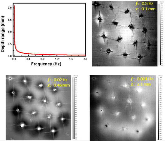
Figure 6: Depth Range for the investigated composite sample and 3 phase images at different depths within the sample.
Quantitative Analysis.
To estimate the defect size, the Reveal Lab coordinate system was calibrated on samples of known size prior to performing NDT experiments. Defect sizes were computed for different depths within the sample.
Central Impact Hole Size.
Figure 7 shows the central impact damage area of all shots as a function of depth range. The projectiles used for the ballistic shots were 5.5 mm in dimeter and about 7 mm in height, corresponding to a base area of about 24 mm2. The mean damage area of the central impact for all shots appear to be quite consistent with the size of the projectile, demonstrating good precision of the quantification done in this work.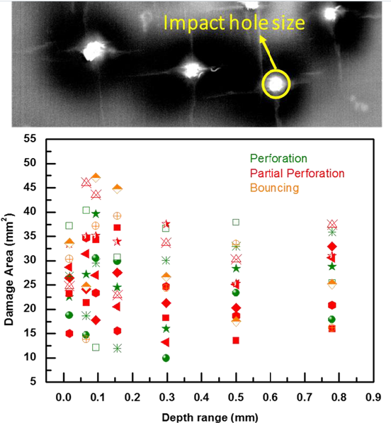
Figure 7: Central impact damage area of all the shots as a function of the depth range.
Total damage size of bouncing shots.
Figure 8 shows the total damage area for three shots (bouncing) as a function of the depth range. The total damage includes the impact hole and regions displaying the fiber delamination and compression/shear induced damage type. Higher velocity shots appear to induce greater damage. Bouncing type shots induce delamination very close to the sample surface but sample damage size quickly decreases with increasing depth. For example, shot 15 does not show any damage at 2.1 mm from the surface of the sample. This allows for an estimation of the depth of the impact damage for Shot 15 to be approximately 1 mm.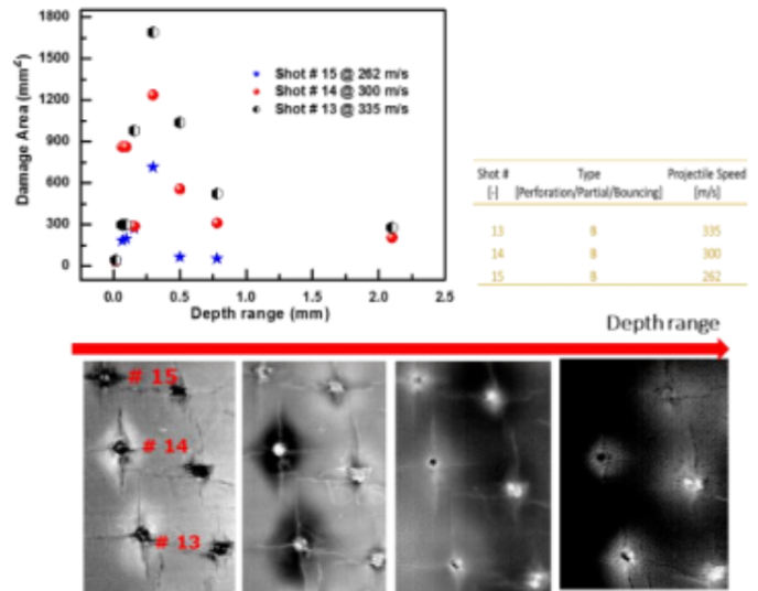
Figure 8: Damage area for three shots (bouncing) as a function of depth range.
Total damage size of partial perforation shot.
Figure 9 shows the total damage area for six shots (partial perforation) as a function of the depth range. Relatively higher delamination damage was observed for lower speed shots (shots 9 and 10) in the case of partial perforation shots. However, for some shots, the projectile remained embedded in the sample after the ballistic impact test, which may have had an undetermined impact on the NDT results. Additional considerations include the effect of sample weakening due to repeated impacts. The sample was subjected to 15 consecutive shots, later shots impacted a sample already weakened by earlier shots. This can be seen when comparing the damage caused by shots 9 and 10 (lower velocity) with shots damage caused by shots 1, 4-6 (higher velocity). Lower velocity shots seem to induce bigger damage. Considerations must therefore be made for impacts recorded in the latter phases of this test to account for potential degradation of overall plate integrity due to previous impacts. Additionally, in this analysis, shots 9-12 generated increased and overlapping areas of delamination damage compared to earlier impacts, potentially due to the plate degradation by earlier shots. These large areas of spread delamination damage complicate efforts to precisely quantify the damage area induced by each shot.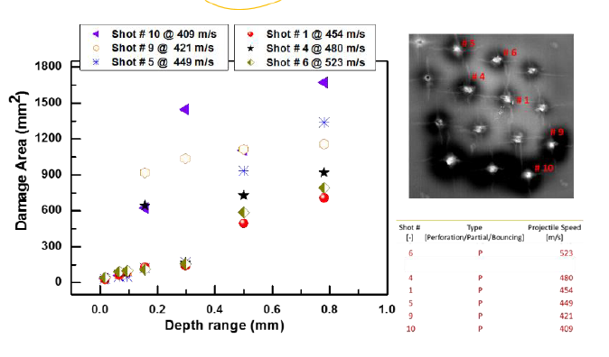
Figure 9: Damage area for six shots (partial perforation) as a function of depth range.
Total damage size of perforation shots
Figure 10 shows the total damage area for four shots (perforation) as a function of depth range as well as phase images measured from both sides of the specimen. The damage size areas shown on figure 10 top left panel were extracted from measurements done on the front side, but same analysis could be done from the rear side as well. At the sample surface (zero depth range), the size of the damage shown in figure 10 top left panel corresponds to the projected penetration hole. At deeper depth range the sample experience delamination, increasing the total damage size. Around 2.1 mm the total damage size decreases due to damping of the delamination propagation. The NDT experimental conditions allow for investigation up to 2.1 mm deep inside the sample from each side of the specimen. Because the composite sample is approximately 5 mm thick, our analysis provides insight into a large portion of the sample cross-section. For the perforation shots, the defect sizes do not vary much with the projectile speed as expected in high velocity ballistic impact conditions. Compared to the partial perforation and bouncing shots, the perforation shots show less delamination damage. When the projectile completely perforates the material more energy is absorbed via the fiber breakage mechanism. Relatively limited delamination damage is therefore observed with corresponding smaller defect size as compared to the partial perforation and the bouncing type.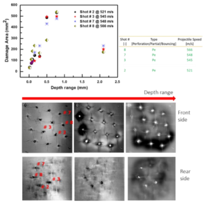
Figure 10: Damage area for four shots (perforation) as a function of the depth range.
Conclusion
Telops offers a complete non-contact infrared active thermography solution which includes a high-capability Telops FAST-IR thermal camera, powerful software, and flexible illumination options including optical, mechanical, and electromagnetic sources. Our NDT solutions ensure high quality industrial and research material analysis. Thanks to the high frame rates of Telops cameras, the TESTD systems can detect damage from corrosion, delamination, decay, and other irregularities even from very thin or from highly conductive or diffusive materials which are notoriously hard to investigate. We conducted quantitative analysis of the damaged areas on composites ballistic plates subjected to high velocity impact. This quantitative defect analysis combined with knowledge of projectile velocity allows for characterization of absorbed energy and differentiation of generated defect types. Our observations indicate that high velocity shots tend to induce smaller impact damage areas characterized primarily by fiber breakage, while low velocity shots tend to induce larger impact damage areas featuring predominantly delamination and matrix cracking damage mechanisms.
References
- Busse G. and Rosencwaig A. “Subsurface Imaging with Photoacoustics,” Appl. Phys. Lett., 36(10):815-816, 1980.
- Thomas R. L., Pouch J. J., Wong Y. H., Favro L. D. and Kuo P. K. “Subsurface Flaw Detection in Metals by Photoacustic Microscopy”, J. Appl. Phys., 51(2): 1152–1156, 1980.
- Meola C et al. J. Mater. Process. Technol., 155-156:1132–1137, 2004.
Telops Inc.
+1-418-864-7808
100-2600 St-Jean Baptiste Ave
sales@telops.com
Québec, QC, Canada, G2E 6J5
www.telops.com


